
- Subscribe to RSS Feed
- Mark as New
- Mark as Read
- Bookmark
- Subscribe
- Printer Friendly Page
- Report Inappropriate Content
1. Overview
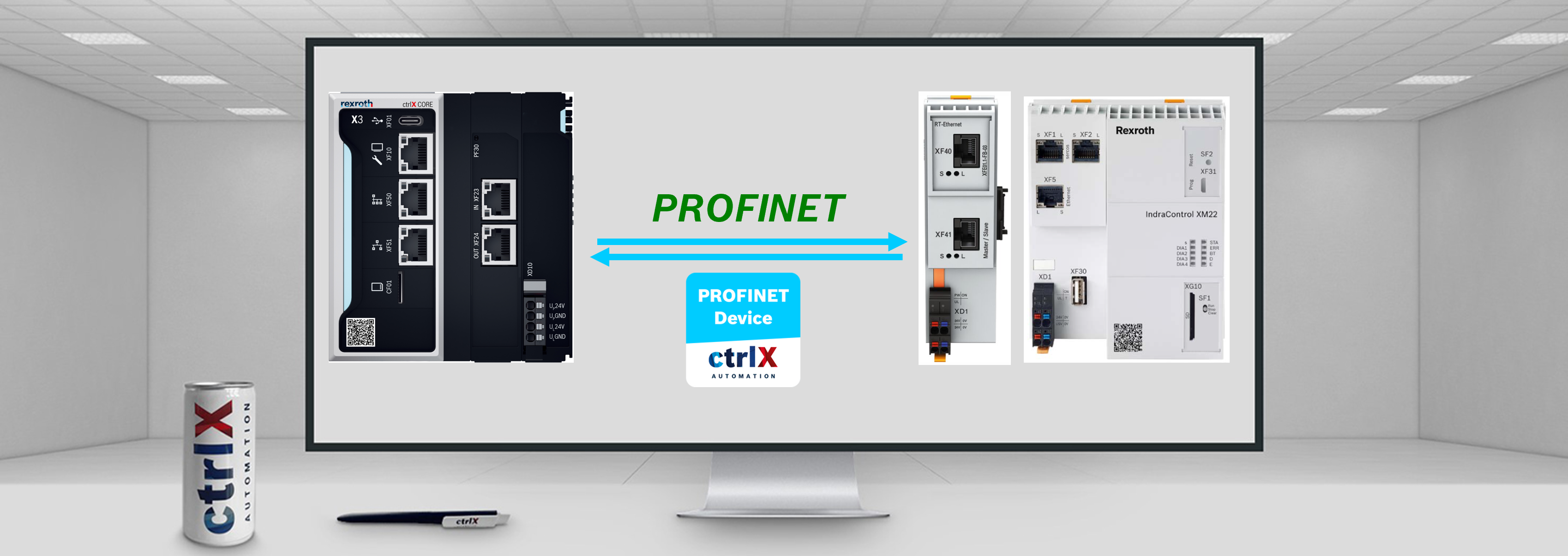
In this tutorial, it will be shown how to connect a IndraControl XM21 with a ctrlX CORE using PROFINET. To be able to connect to the XM21 through PROFINET, an RT-Ethernet extender will be used.

In this case, the ctrlX CORE will act as PN device, and the XM21 will be the PROFINET controller (Master). The XM21 will contain a PLC program that will digitally simulate the inputs and outputs.
2. Prerequisites
- PROFINET Device app
- IndraWorks Engineering program
3. ctrlX CORE configuration
1. First, ctrlX CORE will be connected to the Engineering computer and the ctrlX WORKS program will be started.
- In ctrlX WORKS, check the recognised devices, and enter the ctrlX CORE web interface by clicking over the IP address
2. Install PROFINET device app. Download the app from this link
- To perform this step, it is recommended to follow the instructions shown in the following article.
- The app is installed. In the ctrlX CORE web interface the “Settings” menu is clicked -> Access “Apps” -> Change to “Service mode” because otherwise it will not be possible to install the app, and the “Install from file” button is clicked. A new window will be opened where the previously downloaded file is selected.


3. Add PROFINET device:
- Access the PROFINET device app
- Check that the ctrlX CORE is in “Service” mode (Otherwise it will give an error as shown in the figure)
- “Add PROFINET device”

Error that appears in the case the PROFINET device is added in “Operating” mode

4. Add PROFINET device

5. Configure PROFINET device:
- Click the pencil button
- Select template (this has to be chosen in function of sent data from the connected device to the ctrlX CORE)
- Save configuration

6. Start the communication. 1. Change to “Operating” mode -> 2. Run PROFINET device app

Note: Before connecting both devices it is recommended to check that the ctrlX CORE IP address is of the same type as the XM22 device. In connectivity, change the eth1 to an IP address of a similar type.
4. IndraControl XM21 configuration
Note: It will be assumed that the user knows how to install the IndraWorks Engineering program
1. Connect the IndraControl XM21 to the Engineering computer using the Ethernet port located in the IndraControl XM21 (XF5) and plug it to the computer Ethernet port. Make sure to establish correctly the static IP address. Once done this, open the IndraWorks Engineering program and create a new project:
- Create a new project
- Select "empty project"
- Enter a project name
- Press "Ok"

2. Add device
- Right click over the project name
- Press "Add"
- Select "Add" again
- Choose the type of IndraControl (In this case we will use the IndraControl XM2 series)
- Double click over "IndraControl XM2"

- Step 1: General Properties -> Introduce a device name and press "Next"

- Step 2: Hardware/communication
- Select the Device release
- Select the communication type
- Introduce the XM2 IP address
- Select the PLC gateway
- Test the connection

- Step 3: Extended settings. Keep everything as default

- Step 4: Function packages. Only select "Programmable Logic Control"

- Step 5: Interfaces
- Extensionmodule: In this case only the RT-Ethernet will be used
- sercos: Choose SercosIII Master
- Press "Finish" and wait until the configuration is performed

3. Set PROFINET device
- Right click over "Not_Used"
- Select "Set device"
- Select "PROFINET IO Controller XM"

- Configure the device
- Double click over "PROFINET_IO_Controller_XM"
- Select the "General" tab
- Choose an IP address for the PN-Device
- Configure the IP address range

4. Add PN-Device description: To be able to scan and recognise the Profinet device or to add the PN-Device it is required to install the device description. In this case, the ctrlX CORE description is needed.
- Press the following link and download the ctrlX CORE device description

- Return to IndraWorks Engineering, Select "Tools" -> "Device database"

- Press "Add devices"

- Select the downloaded ctrlX CORE .xml file. Once finished, close the window.
5. Add PN-Device to the devices tree. There are two options to add the profinet device:
1. Scanning the device
NOTE: To be able to scan the devices, these requirements are necessary:
- The ctrlX CORE must be connected to the IndraControl XM21.
- The PROFINET Device app must be running. By pressing the "Run" button in the app it is enough to be able to recognize the ctrlX CORE.
Once, these requirements have been checked, it is possible to scan the ctrlX CORE from the IndraControl XM21. If it does not work, follow the steps by adding the device manually
- Right click over "PROFINET_IO_Controller_XM"
- Select "Scan for devices"

3 Copy the device to the project
As in this "How-To" the ctrlX CORE has been configured with an "in_128_out_128" template, this is the result of the scan.

Reminder: The template can be selected in the configuration menu in the PROFINET Device app in the ctrlX CORE web interface

Troubleshooting:
In the case an error similar to the shown in the following image appears, some additional steps are required to do.

- In the case, no Station name appears, it is necessary to write one name
- An IP address that is in the same subnet as previously configured is necessary to configure. In this case, the 192.168.10.2 IP address will be written
- For the Subnet Mask the 255.255.255.0 address will be configured

- Select the device description
- Press "Set Name and IP"

- Once the button has been pressed, the error should disappear and the device description will appear. As it can be seen, the 128bit output and input that was previously configured in the PROFINET Device app, appears
- Press "Copy All Devices to project" to add them to the project
- Close the window

2. Adding the device manually
- Right click over "PROFINET_IO_Controller_XM"
- Select "Add"
- Select "Add" again

- Select the PLC section
- Double click over ctrlX CORE
- Close the window

- Set up the inputs and outputs
1. Extend the ctrlX CORE tree and start the configuration
- Add output: Right click over "producer" -> "Set device" -> Select "module_out"

- Add input: Right click over "consumer" -> "Set device" -> Select "module_in"

2. Choose the type of variable
- Right click over "module_out" -> "Add" -> "Add"

- Double click over "byte_128_out" and close the window

- Right click over "module_in" -> "Add" -> "Add"

- Double click over "byte_128_in"

- Check the ctrlX CORE IP address and define a station name

6. Write a little program to write values
- Global variables definition
- Double click over "UserVarGlobal"
- Define the variables

- Local variables definition and PLC program

The PLC program is the following:
// Counter
byCounter := byCounter + 1;

// Array element 0..3
FOR iIdx:=0 TO 3 BY 1 DO
// Copy the input bytes to the output bytes
UserVarGlobal.byArray_0_q[iIdx] := UserVarGlobal.byArray_0_i[iIdx];
END_FOR

// array element 4..7
FOR iIdx:=4 TO 7 BY 1 DO
// Fill the arrays with data
UserVarGlobal.byArray_0_q[iIdx] := byCounter + iIdx;
END_FOR
7. Map the variables
- First, the ouput variable will be mapped
- Double click over "byte_128_out"
- Select the I/O Mapping tab
- Expand the tree
- Write the variable desired to map. In this case it will be the "byarray_0_q" in the position 4

Note: To find easier the variable, double click over the black space and select the variable

- The same steps are followed for the input variable:
- Double click over "byte_128_in"
- Select the I/O Mapping tab
- Expand the tree
- Write the variable desired to map. In this case it will be the "byarray_0_i" in the position 4

5. Testing
1. Login and run the PLC program
- Click over the login button

- Accept the message and follow the steps

- Run the PLC program -> Accept the message

Note: In the case the PROFINET Device app is still not working in the ctrlX CORE, the warnings shown in the next image will appear:

- Run the program in the ctrlX CORE, and check the tree again

If the PROFINET communication is working properly, in the PROFINET Device app the "OP" state should be visible

- Check received values in the Data Layer
- Go to "Settings"
- "Data Layer"
- Expand the tree as shown
- Check the realtime values

Note: If the user wants to read these values from the ctrlX WORKS PLC Engineering program, it is recommended to follow the steps shown in this article.
6. Related Links
- PROFINET - CONNECT CTRLX CORE X3 WITH INDRADRIVE
- PROFINET - READ PROFINET DEVICE APP VALUES FROM CTRLX PLC ENGINEERING
- PROFINET - CONNECT CTRLX CORE PLUS X3 WITH INDRACONTROL XM21
- PROFINET - CTRLX CORE X3 WITH CTRLX CORE PLUS X3
- PROFINET - CONNECT CTRLX CORE X3 WITH CTRLX CORE PLUS X3 WITH FIELDBUS LIBRARIES

You must be a registered user to add a comment. If you've already registered, sign in. Otherwise, register and sign in.