
- Subscribe to RSS Feed
- Mark as New
- Mark as Read
- Bookmark
- Subscribe
- Printer Friendly Page
- Report Inappropriate Content
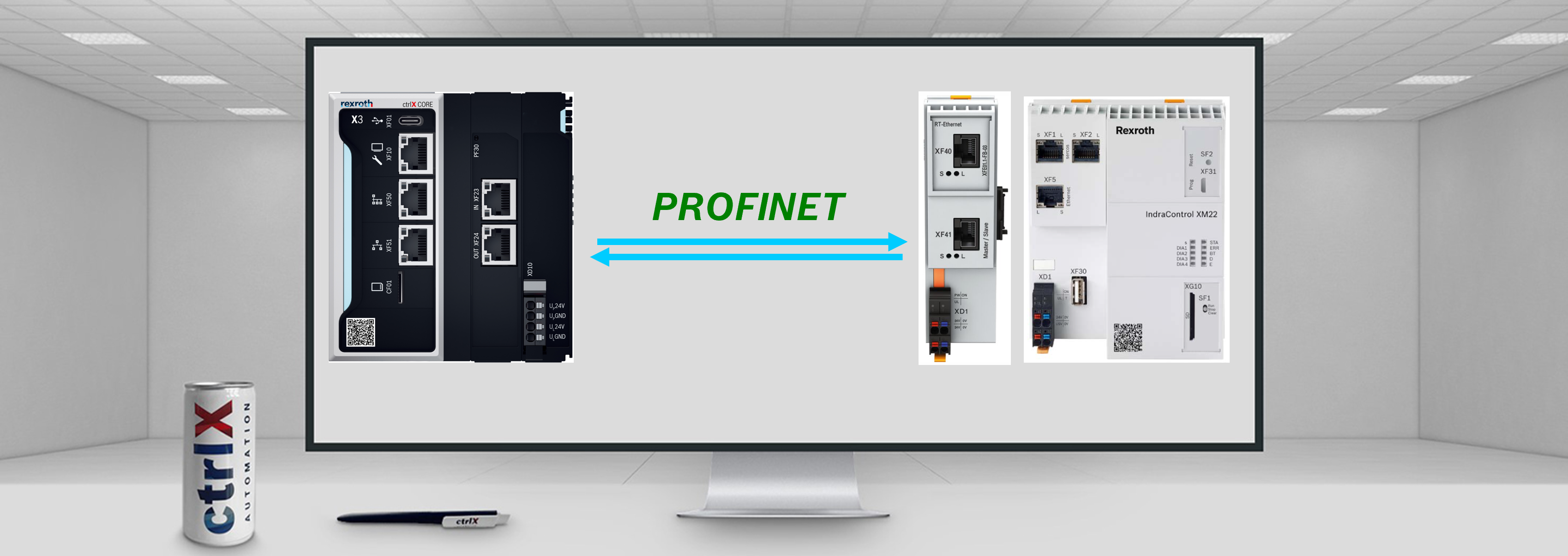
1. Overview
In this article, it will be explained how to connect a ctrlX COREplus X3 with a IndraControl XM21 using the PROFINET connection. This connection can also be done between a ctrlX CORE X3 and an IndraControl XM21. The IndraControl will be first configured using the IndraWorks Engineering program, and the ctrlX CORE will be configured with the CoDeSys Profinet libraries using ctrlX PLC Engineering program.

2. Prerequisites
- ctrlX PLC app
- CoDeSys Fieldbus libraries
- PLC Engineering program
- IndraWorks Engineering program
3. IndraControl XM21 configuration
Note: It will be assumed that the user knows how to install the IndraWorks Engineering program
1. Connect the IndraControl XM21 to the Engineering computer using the Ethernet port located in the IndraControl XM21 (XF5) and plug it to the computer Ethernet port. Make sure to establish correctly the static IP address. Once done this, open the IndraWorks Engineering program and create a new project:
- Create a new project
- Select "empty project"
- Enter a project name
- Press "Ok"

2. Add device
- Right click over the project name
- Press "Add"
- Select "Add" again
- Choose the type of IndraControl (In this case we will use the IndraControl XM2 series)
- Double click over "IndraControl XM2"

- Step 1: General Properties -> Introduce a device name and press "Next"
- Step 2: Hardware/communication
- Select the Device release
- Select the communication type
- Introduce the XM2 IP address
- Select the PLC gateway
- Test the connection

- Step 3: Extended settings. Keep everything as default
- Step 4: Function packages. Only select Programmable Logic Control

- Step 5: Interfaces
- Extensionmodule: In this case only the RT-Ethernet will be used
- sercos: Choose SercosIII Master
- Press "Finish" and wait until the configuration is performed

3. Set PROFINET device
- Right click over "Not_Used"
- Select "Set device"
- Select "PROFINET IO Controller XM"

- Configure the device
- Double click over "PROFINET_IO_Controller_XM"
- Select the "General" tab
- Choose an IP address for the PN-Device
- Configure the IP address range

4. Add PN-Device description: To be able to scan and recognise the Profinet device or to add the PN-Device it is required to install the device description. In this case, the ctrlX CORE description is needed.
- Press the following link and download the ctrlX CORE device description

- Return back to the IndraWorks Engineering program, and select "Tools" -> "Device database"

- Press "Add devices"

- Select the previously unzipped .xml file.

5. Add PN-Device to the devices tree
- Right click over "PROFINET_IO_Controller_XM"
- Select "Add"
- Select "Add" again

- Select the I/O section
- Double click over CODESYS Profinet Device
- Close the window

- Configure CODESYS Profinet Device
- Double click over CODESYS Profinet Device
- Define a station name
- Check the IP address

- Add input:
- Right click over "ctrlx-core-xcr"
- Add
- Module
- Input
- Select "Input 8 Bit"

- Follow the same steps for the output:
- Right click over "ctrlx-core-xcr"
- Add
- Module
- Input
- Select "Output 8 Bit"

6. Write a little program to write values
- Global variable definition
- Double click over "UserVarGlobal"
- Define the variable "counter"

- Program definition
- Double click over "PlcProg (PRG)"
- Define variables
- Write the lines of code:
//Counter
UserVarGlobal.counter := UserVarGlobal.counter + 1;
//Input will take the counter value
input := UserVarGlobal.counter;
//Equal output with input
output := input;

7. Map the variables
- First, the input variable will be mapped
- Double click over "Input_8Bit(Input 8Bit)"
- Select the I/O Mapping tab
- Write the desired variable to map. In this case it will be the "input". To add it it is required to write "Application.PlcProg.input"

Note: To find easier the variable, double click over the black space, expand the tree and double click over the variable

- The same steps are followed for the output variable:
- Double click over "Output_8Bit(Output 8Bit)"
- Select the I/O Mapping tab
- Double click over the blanck space or press over the three points
- Expand the "Application" tree -> Expand the PLC program tree to find the defined variables
- Double click over the "output" variable
- Press "Ok" to close the window

4. ctrlX COREplus X3 configuration
- In this section, it will be shown how the ctrlX COREplus X3 has to be configured. First, connect the ctrlX CORE to the Engineering computer using the Ethernet connection. It is recommended to check the instructions shown in the following link: Quick Start Guide ctrlX CORE
1. Open ctrlX PLC Engineering program and create a new project
- Select "New project"
- Select the ctrlX CORE template
- Provide a project name
- Press "Ok" to close the window

2. Communicate to the ctrlX CORE
- Right click over "Device"
- Select "Communication settings"

- Enter the ctrlX CORE IP address
- Test the connection and cehck the message
- Close the window

Note: Before starting with the communication configuration it is required to install the CoDeSys Fieldbus libraries. Please follow the steps shown here: Manual - CODESYS Fieldbus communication packages for ctrlX CORE. In the case the user has access to the collaboration room, download the packages from this link.
3. Add Ethernet device
- Right click over "Device"
- Select "Add device"

- In the Profinet IO tab -> Ethernet Adapter, select "Ethernet" and press "Add device"

4. Configure Ethernet node
- Double click over "Ethernet"
- Click over "Browse" to find the ctrlX CORE network connections
- Select the "eth1" connection
- Press "Ok" to close the window

- Write the IP address defined in the IndraControl XM21. In this case it was 192.168.10.2. Write the subnet mask (255.255.255.0).

5. Add CoDeSys Profinet device
- Right click over "Ethernet"
- Select "Add device"

- In the Profinet IO Device tree, select "CODESYS Profinet Device" and click over "Add device"

6. Change priorities
Double click over "Profinet_communicationTask" -> Include a priority of 37 as a recommendation

For the "Profinet_IOTask" the same steps are followed:
Double click over "Profinet_IOTask" -> Include a priority of 30 as a recommendation

7. Configure CODESYS Profinet Device
- Double click over "CODESYS_Profinet_Device"
- Select "Use project parameters"
- Write the station name defined in the IndraControl XM21. In this case "ctrlx-core-xcr"

8. Add Input
- Right click over "CODESYS_Profinet_Device"
- Select "Add device"

- In the Profinet IO Module -> Input, select "Input 8Bit" and click over "Add device"

9. Add output
- Right click over "CODESYS_Profinet_Device"
- Select "Add device"
- In the Profinet IO Module -> Output, select "Output 8Bit" and click over "Add device"

- Now that both devices are configured, we are ready to test the connection
5. Testing
1. In the ctrlX PLC Engineering program, generate code and transfer the PLC program to the ctrlX CORE

2. Accept the program creation by clicing over "Yes"
3. Click the Run button

4. In the IndraWorks Engineering, perform similar steps. Click over the login button to transfer the PLC program to the IndraControl XM21

5. Accept the message by clicking over "Yes"
6. Press the Run button

- Accept the message by clicking over "Yes"
Note: If everything works fine, the following symbols should be visible in the PLC Engineering program

- In the case it does not work, perform a "Reset cold" and run the PLC program again

- To check the received values, go to "Output_8bit" and check if the values are updated

- If the values are not updated as shown in the previous image, it is required to follow the steps:
- Unlog
- Select "Enabled 2"

- Login again, run the program, and check the updated values

If still does not work, close the output window and open it again. Or also try to reset cold.
Note: In the IndraWorks Engineering program it is also possible to check the sent values

6. Related Links
- PROFINET - CONNECT CTRLX CORE X3 WITH INDRADRIVE
- PROFINET - READ PROFINET DEVICE APP VALUES FROM CTRLX PLC ENGINEERING
- PROFINET - CTRLX CORE X3 WITH CTRLX COREPLUS X3
- PROFINET - CTRLX COREPLUS X3 WITH INDRACONTROL XM21
- PROFINET - CONNECT CTRLX CORE X3 WITH CTRLX COREPLUS X3 WITH FIELDBUS LIBRARIES
- CODESYS fieldbus add-on installation guide for ctrlX AUTOMATION

You must be a registered user to add a comment. If you've already registered, sign in. Otherwise, register and sign in.