
- Subscribe to RSS Feed
- Mark as New
- Mark as Read
- Bookmark
- Subscribe
- Printer Friendly Page
- Report Inappropriate Content
1. Overview
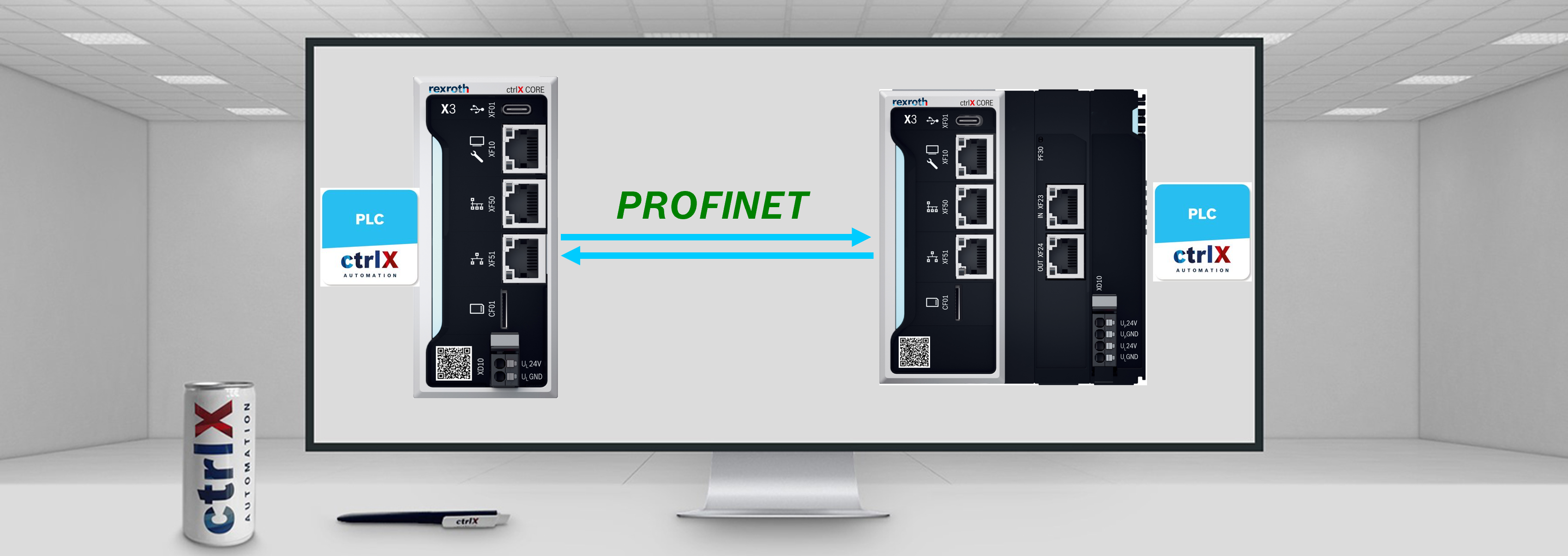
In this article, a ctrlX CORE X3 as a Profinet Controller will be configured to connect with a ctrlX CORE plus X3 that will be a Profinet Device. To be able to establish the connection between both, the CoDeSys Profinet library will be used in both devices. This configuration can also be done between two ctrlX CORE X3 or between two ctrlX CORE plus X3.

2. Prerequisites
3. ctrlX CORE X3 (PN-Controller) configuration
Note: Before starting with the configuration it is required to install the CoDeSys Fieldbus libraries. Please follow the steps shown here: Manual - CODESYS Fieldbus communication packages for ctrlX CORE.
1. Configure IP address:
- First, in the ctrlX CORE web interface, go to the “Settings” menu
- "Connectivity"
- Select the "eth1" connecion
- Select "IPv4"
- Write the desired IP address. NOTE: To avoid conflicts with the web interface IP address (192.168.1.1) an IP address of the type 192.168.2.X will be written. In this case: 192.168.2.12. To configure the subnet mask, the /24 is added
- Save configuration

2. Configure PLC program
- A new project is created: First, select a ctrlX CORE template -> Provide a project name -> Press “Ok”

A new project tree will be created.
- Add drivers to the project: Right click over “Device” and select “Add Device”

- 1. Extend the Profinet IO section and select Ethernet adapter -> 2. Press “Add Device”

- Now the Ethernet node should be visible in the Device tree

- Communicate to the ctrlX CORE
Right click over "Device" -> "Communication settings" -> Enter ctrlX CORE IP Address -> Test connection by pressing over the "Run" button -> Press “Ok”

- Configure Ethernet Node
First, double click over "Ethernet" -> 2. Press “Browse” -> 3. Select "eth1" where the previously configured IP address should be visible -> 4. Press “Ok”

- Add PN Controller
- Right click over “Ethernet” -> "Add device"
- Select PN-Controller in the Profinet IO Master section
- Press “Add device”

- Change priorities.
Double click over "Profinet_communicationTask" -> Include a priority of 37 as a recommendation

For the "Profinet_IOTask" the same steps are followed:
Double click over "Profinet_IOTask" -> Include a priority of 30 as a recommendation

- Configure PN Controller
Double click over "PN_Controller" -> Provide a PN-Controller station name (By default the name will be controller) -> Configure Slave IP Parameters

- Add Profinet device
- Right click over "PN_Controller" -> "Add Device"
- Expand the I/O folder -> CODESYS PLC -> Select CODESYS PROFINET Device
- "Add device"

- Configure PN-Device:
- Double click over CODESYS_Profinet_Device
- Give the station name configured in the PN Device
- Write the configured IP address in the PN Device (In this case, 192.168.2.13)
NOTE: Notice that PN-Controller and PN-Device have the same IP 192.168.2.X type. Otherwise, it would not work.

- Add IO to read the sent values:
- Right click over "CODESYS_Profinet_Device" -> "Add device"
- Select "Output 8bit" because this will be the type of data sent from the PN-Controller to the PN-Device
- Press “Add device”

NOTE: If the PN-Device is already configured and connected, there is other way to add the Profinet Device to the project. Login to the ctrlX CORE

NOTE: You can also run the program, but it is not required to scan the profinet devices

Once the PLC program has been transferred to the ctrlX CORE:
- Right click over “PN_Controller” -> "Scan Devices"
- In the case it has not scanned the devices -> "Scan Devices"
- The device should appear with its outputs
- Copy al the devices to object

- The PN-Device should appear in the device tree

Troubleshooting: In the case, the PN-Controller is not able to scan the PN-Device, reset cold the PLC program in the PN-Device.
- Write little program to send data:
- Double click over "PLC_PRG" in the device tree
- Define the variables
- Write the program

- Map the program variable with the output:
- Double click over "Output_8Bit"
- Select the PNIO Module I/O Mapping tab
- Double click over the USINT type variable
- Look for the counter variable and select it
- Press “Ok”

Once everything has been configured, the following window should appear:

Before testing the PLC program, it is required to configure the PN-Device. Keep the window open because later it will be used to check the sent values.
4. ctrlX CORE plus X3 (PN-Device) configuration
1. Configure IP address
- First, in the ctrlX CORE web interface, go to the “Settings" menu
- "Connectivity"
- Select the "eth1" connection
- Select "IPv4"
- Write the desired IP address. NOTE: To avoid conflicts with the web interface IP address (192.168.1.2) an IP address of the type 192.168.2.X will be written. In this case: 192.168.2.13 because the defined IP address by the PN-Controller was this one. To configure the subnet mask, the /24 is added
- Save configuration IMPORTANT: Write an IP address different to the one configured in the PN-Controller
NOTE: This step is not mandatory because with the configuration performed in the PLC program, it will be enough. In this case it would create a dynamic IP address.

2. Configure PLC program
- A new project is created: First, select a ctrlX CORE template -> Provide a project name -> Press “Ok”

- A new project tree will be created.
Add drivers to the project: Right click over “Device” and select “Add Device”

- 1. Extend the Profinet IO section and select "Ethernet" -> 2. Press “Add Device”

- Now the Ethernet node should be visible in the Device tree

- Communicate to the ctrlX CORE:
- Right click over "Device" -> "Communication settings"
- Enter ctrlX CORE IP Address
- Test connection by pressing the Run button
- Press “Ok”

- Configure Ethernet Node:
- First, double click over "Ethernet"
- Press “Browse”
- Select "eth1" where the previously configured IP address should be visible
- Press “Ok”

NOTE: In the case, the IP address was not configured in the ctrlX CORE web interface, select also the eth1 option, but the IP address will be 0.0.0.0. Later, it is required to fill the following spaces:

Write the PN-Device address defined in the PN-Controller (192.168.2.13) and write the subnet mask.
When following these last steps in the eth1 connectivity overview, a dynamic IP address will be visible:

Otherwise, this would be the overview:

- Add PN Device
- Right click over “Ethernet” -> "Add device"
- Select "CODESYS Profinet Device"
- Press "Add device"

- Change priorities.
Double click over "Profinet_communicationTask" -> Include a priority of 37 as a recommendation

For the "Profinet_IOTask" the same steps are followed:
Double click over "Profinet_IOTask" -> Include a priority of 30 as a recommendation

- Configure PN Device:
- Double click over "CODESYS_Profinet_Device"
- Change to “Use project parameters”
- Write the previously defined station name for the PN_Device. In this case PN_Device-plus_X3

- Add Output
- Right click over "CODESYS_Profinet_Device" -> "Add device"
- Select "Output 8bit"
- Press “Add device”

NOTE: To be able to read the sent values from the PN-Controller to the PN Device it is required to write a line of code in the PLC_PRG as follows:

The IB1 value is the output address of the output which can be found as follows:

5. Testing
NOTE: To be able to use the PLC programs in both ctrlX COREs, it is required to be in “Running” mode
From the ctrlX CORE plus X3 side, the PLC program is transferred to ctrlX CORE. Press the “login” button and later the “Run” button

From the ctrlX CORE X3 side, the PLC program is transferred by following the same step as for the ctrlX CORE plus X3.

Once executed: in the device tree the symbols shown in the following image should be visible.

As seen in the previous figure, the output values are not updated and to be able to see them, it is required to perform the following steps:
1. Unlog and select the “Enabled 2 (always in bus cycle task)" option. Once done this, log again and check if the values are updated.

As it can be seen, now the values are updated. In the case, they still do not appear, perform a reset origin and try again

From the ctrlX CORE X3 side, perform the same steps and check how all the data is sent.

6. Related Links
- PROFINET - CONNECT CTRLX CORE X3 WITH INDRADRIVE
- PROFINET - READ PROFINET DEVICE APP VALUES FROM CTRLX PLC ENGINEERING
- PROFINET - CONNECT CTRLX CORE PLUS X3 WITH INDRACONTROL XM21
- PROFINET - CTRLX CORE PLUS X3 WITH INDRACONTROL XM21
- PROFINET - CONNECT CTRLX CORE X3 WITH CTRLX CORE PLUS X3 WITH FIELDBUS LIBRARIES

You must be a registered user to add a comment. If you've already registered, sign in. Otherwise, register and sign in.