
- Subscribe to RSS Feed
- Mark as New
- Mark as Read
- Bookmark
- Subscribe
- Printer Friendly Page
- Report Inappropriate Content
Introduction
In the following we show to you how to commission 3rd party motors with ctrlX DRIVE.
The possible solutions are to control:
- Asynchronous motors without encoder in open loop over U/f control for simple, non-demanding and non-dynamic applications
- Asynchronous motors without encoder in open loop over SVC control for medium demanding and medium dynamic applications
- Synchronous motors without encoder in open loop over SVC control for medium demanding and medium dynamic applications
- Asynchronous or synchronous motors with encoder in closed loop over FOC control for demanding and high dynamic applications
If the motors are linear or rotatory doesn´t matter.
All the functions and screen shots are based on:
- ctrlX DRIVE Engineering version 01V10
- Runtime / Firmware version of drive AXS-V0302 or
- Runtime / Firmware version of drive AXS-V0208
Prerequisites
A connection to the ctrlX DRIVE has been successfully establi-shed, the device is correctly wired and 24 V are successfully put on. As well the engineering tool ctrlX DRIVE Engineering has been started.
Mind that additional prerequisite like minimum inductance of
motor in relation to chosen converter or inverter size depending on the later-on used PWM frequency has been checked.
Similar, that the chosen encoder or linear scale, if using closed loop control, is been able to be evaluated with the used hardware and firmware (runtime) version.
1. Principle commissioning of 3rd party motors
1.1. Prior settings
Before starting the sequence for principle commissioning of 3rd party motors the prior settings for
- Encoder
- Operation modes
- Drive Halt
- Limitations
- Drive control method
should be adjusted according to the later operation or use.
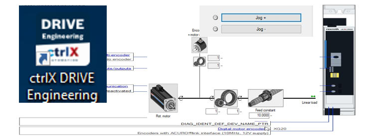
1.1.1. Encoder settings

Fig. 1.: Encoder settings
1.1.2. Operation modes settings
The operation mode should be selected like the later use is planned.
Mind, that, if operating a motor without encoder, operation modes requesting an encoder (like position control mode) are not possible.

Fig. 2.: Selection of operation modes
1.1.3. Drive Halt settings
Set the drive halt acceleration according to your application. Jerk is recommended to be set to “0”.

Fig. 3.: Drive Halt settings
1.1.4. Torque/force limitation settings
Check the limitation settings to protect the mechanics or the drive package.

Fig. 4.: Limitation settings
1.1.5. Drive control method settings
The drive control method should be set according to the later usage.

Fig. 5.: Selection of “Control method”

Fig. 6.: Selection of “Motor operation configuration”
1.2. Initial commissioning sequence of 3rd party motors
Underneath the node “Motor” and “Motor type” in the project tree a sequence for “Initial motor commissioning” can be started.

Fig. 7.: Start “Initial motor commissioning”
1.2.1. Motor data
In step 1 select the type of motor present and if encoder, temperature sensor or brake is present. Depending on this selection, the number of steps for commissioning is been adjusted.

Fig. 8.: Step 1: Selection of motor type and encoder, temperature sensor or brake, if present
In step 2 enter the data for the motor provided by the motor manufacturer.

Fig. 9.: Step 2: Motor data input (1)

Fig. 10.: Step 2: Motor data input (2) (advanced data)
Then press the button “Calculate motor control parameters”!

Fig. 11.: Step 2: “Calculate motor control parameter” (only possible in “OM”)
1.2.2. Encoder data (if present)
Next step is to enter the motor encoder data.

Fig. 12.: Step 3: Parameterization of motor encoder
The mechanical attachment of the motor encoder to the motor has to be parameterized.

Fig. 13.: Step 4: Mechanical attachment of motor encoder
1.2.3. Temperature monitoring / Temperature sensor
The parameters for temperature monitoring of the motor have to be set. If no temperature sensor is used, at least the temperature model data have to be parameterized. The effective behavior can be checked in the motor temperature model.

Fig. 14.: Setting motor temperature monitoring

Fig. 15.: Step 5: Setting motor temperature model parameters

Fig. 16.: Motor temperature model behavior
1.2.4. Brake (if present)
If a brake is present enter the relevant data!

Fig. 17.: Step 5: Brake settings
1.2.5. Validity check of motor parameters
In the next step, the plausibility of the motor and encoder settings are checked. Press the button “Validity check of motor and encoder parameterization”!

Fig. 18.: Step 6: Validity check of motor and encoder parameterization (1)
If in operation mode “OM” and “Ab”, the drive is changing to “AF” and performing some movements.

Fig. 19.: Step 6: Validity check of motor and encoder parameterization (2)
If principle setting of motor data and encoder are correct, the command is executed successfully. If not, the original parameters have to be changed to correct values.
1.2.6. Determining motor data
The motor data are identified via the drive. Select the method and press button “Automatic identification of the motor data”!

Fig. 20.: Step 7: “Automatic identification of the motor data” (1)
If in operation mode “OM” and “Ab”, the drive is changing to “AF” and performing some movements.

Fig. 21.: Step 7: “Automatic identification of the motor data” (2)
Motor resistance and inductance parameters are changed to the measured values in the background.
1.2.7. Commutation setting (if synchronous motor is operated with encoder)
Synchronous motors, if operated with encoders or linear scales, need to determine their commutation (alignment of electric field to magnetic field). For most synchronous motor, except on ironless linear motors, the suitable method is to do this commutation routine using the so-called “Saturation method”. For ironless linear motors the “Sine-wave” method is to be chosen.
Select the proper method!

Fig. 22.: Step 8: Commutation method setting
With the start value "0" for "Amplitude", the motor-specific values for "Amplitude" and "Frequency" are automatically determined. If in operation mode (OM) and “Ab”, check the “Initial commissioning mode” and then press button “Determine commutation offset”!

Fig. 23.: Step 9: Commutation settings (1)
Some current is applied and the commutation offset determined. If routine was successful, uncheck the “Initial commissioning mode” again!

Fig. 24.: Commutation settings (2)
1.2.8. Limitation settings
Next step is to check and eventually correct the limitation figures both for speed and torque/force.

Fig. 25.: Step 10: Limitation settings
1.2.9. Homing (set absolute reference of encoder 1)(if needed)
Then the axis should be homed using the drive-controlled homing procedure or the absolute reference should be set.

Fig. 26.: Step 11: Homing or Set absolute position
1.2.10. First movements
Finally the motor should be moved using the “Easy Startup” mode.

Fig. 27.: Step 12: Start “Easy startup” mode

Fig. 28.: Step 12: Enable the motor
Enter a proper speed for jogging! Then start jogging in the desired direction!

Fig. 29.: Step 12: Input proper speed

Fig. 30.: Step 12: Jog in desired direction
If everything is fine, finish the commissioning sequence of 3rd party motors.

Fig. 31.: Step 12: Finish commissioning sequence for 3rd party motors
1.3. Check of regulation loops and their behavior
Now follow the routine for first setup to set the limitations and directions correctly, autotune and check the regulation loops. The positioning behavior should be checked as well. See:
- 1st setup and execute initial movements
- video 1
- video 2
- blog entry
- Autotuning
- video
- blog entry - Check positioning movements
- video
- blog entry
1.3.1. Check of current loop (not possible in open loop control)
Check and adjust the settings, if needed, by obtaining frequency response diagram.
The bandwidth at -3 dB should be higher than 1000 Hz in dynamic servo axis, in more simple applications like handling 500 Hz may be sufficient.
1.3.2. Check of velocity loop
Check and adjust the settings, if needed, by obtaining frequency response diagram. Especially the filters may be set to suppress resonances in the mechanics. Mind that this filter settings is not possible in U/f control.
The usual stability limits for regulation loops should be adjusted:
In closed loop frequency diagram (blue line diagram):
- Bandwidth is measured at amplitude – 3dB in
- Amplitude shouldn´t exceed + 5dB line
- At higher frequencies than bandwidth amplitude shouldn´t get positive again à indication for resonance causing vibration
Recommendation for phase margin measured at 0 dB of open loop frequency diagram (purple line diagram, cursor 1)
- 40° to 70° for good command response behavior
- 20° to 50° for good load response behavior
- 40° to 60° for well balanced
Recommendation for amplitude margin measured at 0 dB of open loop frequency diagram (purple line diagram, cursor 2)
- Minimum + 5dB
- Usually at least + 10dB for well balanced loop settings

Fig. 37.: Frequency response of velocity loop (not possible to obtain with axes operated in open loop (without encoders))
The usual behavior for step responses should be adjusted
- Overshoot not exceeding 1,4 times the command value
- No vibration visible at coming to commanded speed

Fig. 38.: Step response
1.3.3. Check of position loop (not possible in open loop control)

Fig. 39.: Position loop settings

Fig. 40.: Frequency response of position loop
If running a typical cycle the maximum model deviation is shown. With some safety margin (factor 1,5 to 2,0) the monitoring window should be keyed in!
The velocity loop monitoring should always be active.

Fig. 41.: Loop monitoring
1.4. Further settings
1.4.1. Error reaction settings
The error reaction settings should be set according to the application!

Fig. 42.: Error reaction settings
1.4.2. Status message settings
The status message settings should be set according to the application!

Fig. 43.: Status message settings
2. Specialties for control of 3rd party motors in open loop
2.1. Asynchronous motors using U/f control
For simple, non-demanding and non-dynamic open loop applications (no encoder required) asynchronous motors maybe controlled over U/f control.
As a prerequisite the encoder settings should be set to "No encoder".
All operation modes should be set to “Velocity control”.
The control method has to be set to “Open-loop drive control”!

Fig. 44.: Drive control overview
Eventually the maximum stator frequency slope should be limited.

Fig. 45.: Settings in “Motor operation configuration”
Then the “Initial motor commissioning” should be started. Choose “Asynchronous motor” and follow the steps!
Set “search mode” only, if needed, e.g. if motor could still be running if applying the drive enable signal.
2.2. Asynchronous motors using SVC control
For medium demanding and medium dynamic open loop applications (no encoder required) asynchronous motors maybe controlled over SVC control.
As a prerequisite the encoder settings should be set to "No encoder".
All operation modes should be set to “Velocity control”.
The control method has to be set to “Closed-loop drive control”!

Fig. 46.: Drive control overview
The Motor mode – motor control should automatically be set to “sensorless” (SVC: sensorless vector control).

Fig. 47.: Settings in “Motor operation configuration”
Then the “Initial motor commissioning” should be started. Choose “Asynchronous motor” and follow the steps!
2.3. Synchronous motors using SVC control
For all open loop applications (no encoder required) synchronous motors have to be controlled over SVC control. This is suitable for medium demanding and medium dynamic applications.
As a prerequisite the encoder settings should be set to "No encoder".
All operation modes should be set to “Velocity control”.
The control method has to be set to “Closed-loop drive control”! and the "Motor mode – motor control" should automatically be set to “sensorless” (SVC: sensorless vector control).
Then the “Initial motor commissioning” should be started! As motor category the “Standard synchronous motor” has to be selected!
As Flux-generating current, limit value, 2- to 3-times the motor current at standstill is recommended to enter. The nominal and maximum figures should be known from the motor manufacturer.
3. Specialties for control of 3rd party motors in closed loop (FOC control)
3.1. Asynchronous motors
As a prerequisite the encoder settings should be selected according to the application.

Fig. 48.: Parameter settings of encoder for synchronous motor in FOC control
The operation modes should be set according to later use!
The control method has to be set to “Closed-loop drive control”!

Fig. 49.: Drive control overview
The Motor mode – motor control should be set to “with encoder” (FOC: field oriented control).

Fig. 50.: Settings in “Motor operation configuration”
Then the “Initial motor commissioning” should be started! As motor category the “Asynchronous motor” has to be selected!
3.2. Synchronous motors
As a prerequisite the encoder settings should be selected according to the application.
The operation modes should be set according to later use!
The control method has to be set to “Closed-loop drive control”!
The Motor mode – motor control should be set to “with encoder” (FOC: field oriented control).
Then the “Initial motor commissioning” should be started! As motor category the “Standard synchronous motor” has to be selected!

You must be a registered user to add a comment. If you've already registered, sign in. Otherwise, register and sign in.