- Subscribe to RSS Feed
- Mark as New
- Mark as Read
- Bookmark
- Subscribe
- Printer Friendly Page
- Report Inappropriate Content
In the following we show to you how to best use axis error compensation at ctrlX DRIVE.
Versions used
All the functions and screen shots are based on:
- ctrlX DRIVE Engineering version 01V16
- Runtime / Firmware version of drive AXS-V0308
Prerequisites
A connection to the ctrlX DRIVE has been successfully establi-shed, the device is correctly wired and 24 V are successfully put on. As well the engineering tool ctrlX DRIVE Engineering has been started.
1. What the function is good for
The axis error compensation diminishes the errors of an axis resulting from the tolerances of
- the mechanical design like the pitch error of a ball rail,
- the encoder(s) or
- the linear scal(s).
This allows a more accurate positioning and therefor allows more precise processes and machining, e.g. to improve
- the quality in milling/turning at machine tools
- the accuracy in grinding operations at machine tools
- the printing quality in printing machines
- the positioning accuracy in packaging machines
- the positioning accuracy in precise handlings systems
2. Prerequisite for using the precision axis error correction function
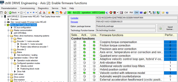
In order to activate the function the so-called productivity package must be present. It should normally already be ordered correctly or, if not ordered, be licensed afterwards by “Import license”.
The “Precision axis error correction” function itself then need to be selected and activated by a “Reboot”.
Fig. 1.: Productivity package with activated function “Precision axis error correction”
Mind that the overall performance of the drive is restricted to not allow more than eight performance points in total shown in the last column. In the example shown in Fig. 1 already eight performance point functions are selected in total. So no additional performance point costing function can be activated additionally.
3. Configure parameters
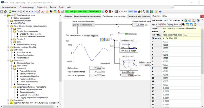
The precision axis error correction is activated by
- defining a start position (in here -330 mm) and
- defining a distance from correction point to correction point
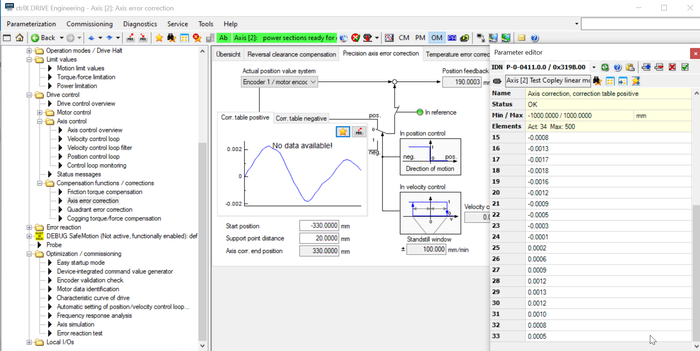
After entering the correction values in the positive and negative correction table the axis error end position is automatically calculated by the number of correction points. In here this is +330 mm as 34 correction points from line 0 to 33 are entered.
Fig. 2.: Configuration for “Precision axis error correction” (1)
Fig. 3.: Configuration for “Precision axis error correction” (2)
4. Learn correction table
Correction table learned in positive direction
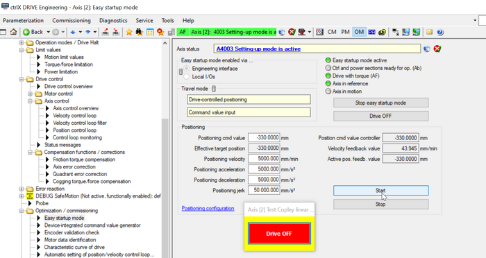
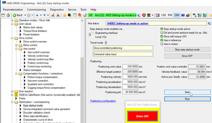
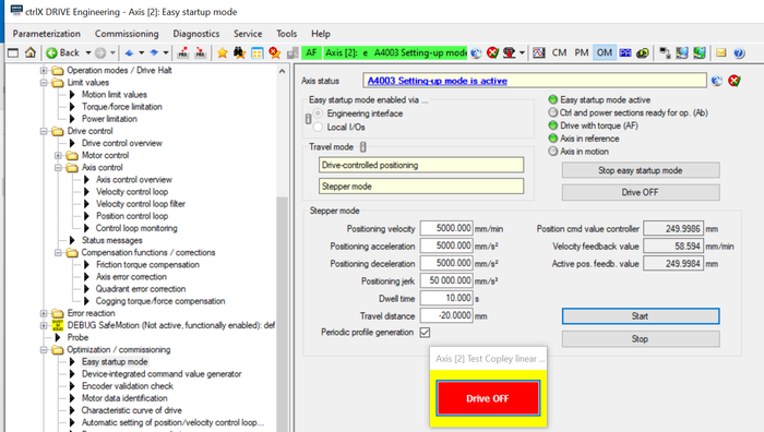
The precision axis error correction tables are simplest learned by using the “Easy Startup Mode” inside the drive. Prerequisite is that the axis is already in reference. Start “Easy Startup Mode”, select “Drive-controlled positioning”, use “Command value input”, key in the start position
(in here -330 mm) then press button “Drive On”!
Fig. 4.: Easy Startup Mode using “Drive-controlled positioning” with Command value input to get to starting point in positive direction
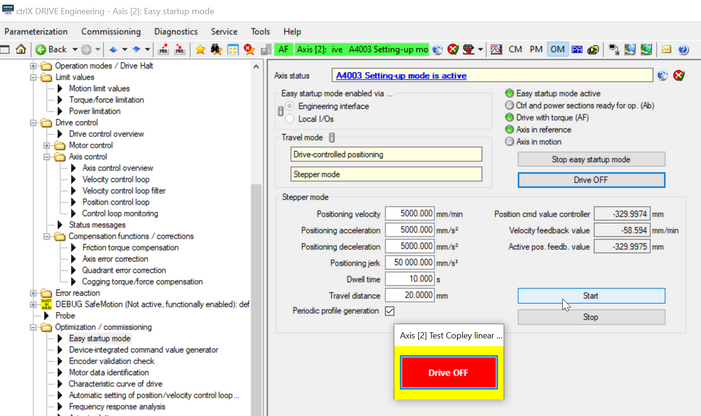
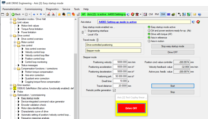
Press “Start” button! After reaching start point, press button “Drive OFF”, select “Stepper mode”, key in right distance like configured as correction points, press button “Drive ON” and start move by pressing “Start” button
Fig. 5.: Start “Stepper mode” move and write down errors at end of each stepper movement visible in e.g. the laser interferometer (in here start point is -330 mm)
Fig. 6.: In “Stepper mode” move at in here point -270 mm error table point is written down using the exact laser interferometer position
Correction table learned in negative direction
Similarly this process is done to obtain the negative error correction points.
Fig. 7.: Easy Startup Mode using “Drive-controlled positioning” with Command value input to get to starting point in negative direction
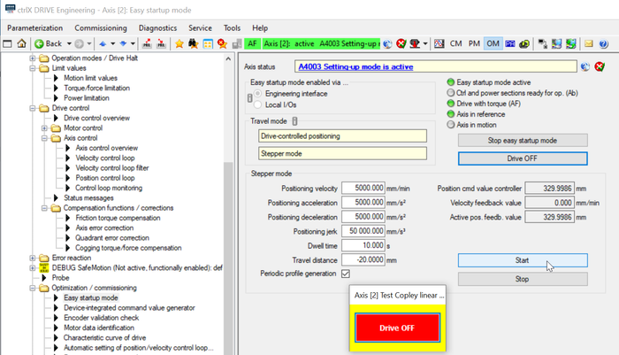
Press “Start” button! After reaching start point, press button “Drive OFF”, select “Stepper mode”, key in right distance like configured as correction points, press button “Drive ON” and start move by pressing “Start” button
Fig. 8.: Start “Stepper mode” move and write down errors at end of each stepper movement visible in e.g. the laser interferometer (in here start point is +330 mm)
Fig. 9.: In “Stepper mode” move at in here point +250 mm error table point is written down using the exact laser interferometer position
5. Activate and check correction table
The precision axis error correction is activated by
- defining a start position (in here -330 mm) and
- defining a distance from correction point to correction point
Fig. 10.: Activate correction table
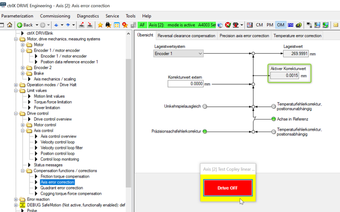
If moving to a position (in here +270 mm) the active correction value is shown in this screen (in here the correction value is 0,0015 mm).
Fig. 11.: Check correction figure
You must be a registered user to add a comment. If you've already registered, sign in. Otherwise, register and sign in.


