
- Subscribe to RSS Feed
- Mark as New
- Mark as Read
- Bookmark
- Subscribe
- Printer Friendly Page
- Report Inappropriate Content
In the following we show to you how to control the STO function of ctrlX DRIVE and a safe door via ctrlX SAFETY in using digital I/Os.
All the functions and screen shots are based on:
- ctrlX SAFETY Engineering version >= 1.7.1.8190
- SAFEX Runtime / Firmwareversion >= 1.0.0.1 (C-sample)
- ctrlX DRIVE Engineering version 01V14
- Runtime / Firmware version of drive AXS-V-0306
or
- Runtime / Firmware version of drive AXS-V-0210
Prerequisites
A connection to the ctrlX SAFETY control and ctrlX DRIVE has been successfully established, the devices are correctly wired and 24 V are successfully put on. As well the engineering tools ctrlX SAFETY and ctrlX DRIVE Engineering have been started.
1. Function of the established SAFEX logic program
The principle function of the SAFEX logic program is the following:
If at the ctrlX SAFETY the EMERGENCY STOP button is pressed or the ModeSelector is switched, the non-safety-functional E-Stop function at the drive is activated immediately, which leads to a deceleration of a still moving axis. With a time delay of in here chosen 0,5 s, which is the time the axis needs to stop in worst case, the SAFEX control activates the safe STO function at the drive which prohibits a further movement. If the drive acknowledges the standstill (which is a non-safety-function only) already before the 0,5 s are exceeded, the safe STO function is directly activated after the drive acknowledges this standstill condition. The door is opened.
If the EMERGENCY STOP button is released and the door is shut again, the Reset button needs to be pressed twice that the EMERGENCY STOP and thus the STO function is released again as well. Then the drive can be activated again.
If only the ModeSelector has been switched and is now switched back again, when the door is shut, the Reset button needs to be pressed once. Then the STO function is released and the drive can be activated again.
Timing diagrams
The following timing diagram shows the sequence for the functionality:

Fig. 1.: Timing diagram with normal behavior at pressing EMERGENCY STOP button (axis is in movement but reaches standstill more quickly than time foreseen)

Fig. 2.: Timing diagram with behavior at pressing EMERGENCY STOP button (axis is in movement but doesn´t reach standstill in the time foreseen)
The timing diagram for switching the ModeSelect is exactly the same like as for pressing the EMERGENCY STOP button.

Fig. 3.: Timing diagram after releasing EMERGENCY STOP button

Fig. 4.: Timing diagram after switching ModeSelect back
2. Wiring schematics
The SAFEX control´s input devices are:
- One double channel EMERGENCY STOP button fed by pulsed 24V
- One double channel Mode Select switch fed by pulsed 24V
- One single channel reset button fed by non-pulsed 24V
- Two single channel inputs coming from two ctrlX DRIVE indicating that standstill is achieved
- Double channel “Door closed” contacts from the safety door
- Double channel “Door locked” contacts from the safety door
All double channel buttons are fed by pulsed 24V
The output devices are:
- One single channel output for control of so-called E-Stop function of drives (quick changeover to standstill)
- Two OSSD fed outputs connected to double channel STO input of drives
- 1 single channel output to open the safety door

Fig. 5.: Wiring schematics
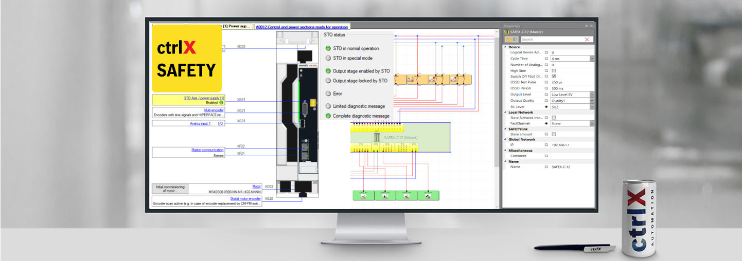
3. Settings inside SAFEX control
The settings of the SAFEX control and the devices connected to the ctrlX SAFETY control should be according to the following.

Fig. 6.: Settings of SAFEX control

Fig. 7.: Settings of “Emergency Stop” button connected to SAFEX control

Fig. 8.: Settings of “ModeSelect” switch connected to SAFEX control

Fig. 9.: Settings of “Start/Reset” button connected to SAFEX control


Fig. 10.: Settings of “Drive standstill” inputs connected to SAFEX control

Fig. 11.: Settings of “Door closed” contacts connected to SAFEX control

Fig. 12.: Settings of “Door locked“ contacts connected to SAFEX control

Fig. 13.: Settings of E-Stop output of SAFEX control
Mind that the E-Stop is not using an OSSD output.
In order to achieve this, the property SIL Level of the SAFETY control needs to be set to SIL2 (see Fig. 6). Then the Output type may be selectable with Standard (see in here Fig. 13)”.
If using OSSD outputs the overall SIL Level for those safety functions is SIL3, even if only SIL2 is been selected.


Fig. 14.: Settings of STO outputs of SAFEX control

Fig. 15.: Settings of “OpenDoor” output of SAFEX control
4. Safe logic inside SAFEX control
The safe logic inside the SAFEX control is created according to the following schematics.

Fig. 16.: Safe logic inside SAFEX control

Fig. 17.: Settings of Restart block

Fig. 18.: Settings of Timer (in here as delay time 0,5 s is chosen, in your application this time may differ)
The corresponding Safe logic program is available for download at the end of the blog.
5. Wiring of ctrlX DRIVE
The wiring of ctrlX DRIVE with STO is done according to the following:

Fig. 19.: Wiring of ctrlX DRIVE with STO
6. Settings of ctrlX DRIVE
The settings inside ctrlX DRIVE are done according to the following:

Fig. 20.: Settings of ctrlX DRIVE (1): I/O signal settings

Fig. 21.: Settings of ctrlX DRIVE (2): Error reaction settings

Fig. 22.: Settings of ctrlX DRIVE (3): E-Stop reaction settings
The corresponding ctrlX DRIVE parameter sets are attached at the end of the blog.

You must be a registered user to add a comment. If you've already registered, sign in. Otherwise, register and sign in.