- Subscribe to RSS Feed
- Mark as New
- Mark as Read
- Bookmark
- Subscribe
- Printer Friendly Page
- Report Inappropriate Content
In the following we show to you, how you can work with the panel. Technical data you may find in the ctrlX DRIVE documentation.
Prerequisites
Please use the current panel hardware version XDP1-N-128-NN-VSRSN-NN (R911403470), USB-C cable and ctrlX DRIVE!
You have to wait 20 sec. until the start screen is shown.
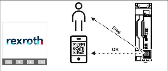
The QR code can be evaluated by using the so called Digital Service Assistant app.
1. Operating modes
In contrast to the currently used display at IndraDrive there are 3 different operating modes.
The activation of each mode starts with the respective connection.
Any point in time, the panel will be in one of the operation modes.
The panel is not designed for multiple modes of operation at same time.
1.1 Panel Engineering mode
Panel engineering mode is activated, when panel is connected to drive.
At power on, panel displays the so called “welcome screen”.
You have to wait for 20 seconds which the panel needs for starting up.
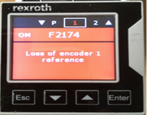
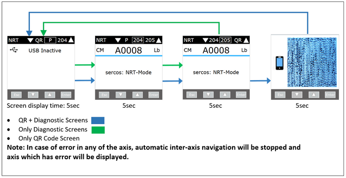
The displayed diagnostics are changing automatically in between:
- Panel diagnostics
- Axis diagnostics
- QR code with information about the current device diagnostics
1.2 USB Engineering mode
Activated, when panel is connected with drive & PC. USB – C cable needed!
In this mode of operation, Panel works as an Ethernet gateway between device and USB host (PC).
1.3 USB mass storage mode
When panel is connected only with the PC, USB mass storage mode is activated.
This welcome screen is displayed unlimited.
Please notice, that you have to do the complete panel firmware handling in this mode.
2. Screen overview
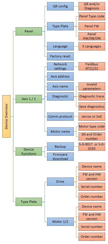
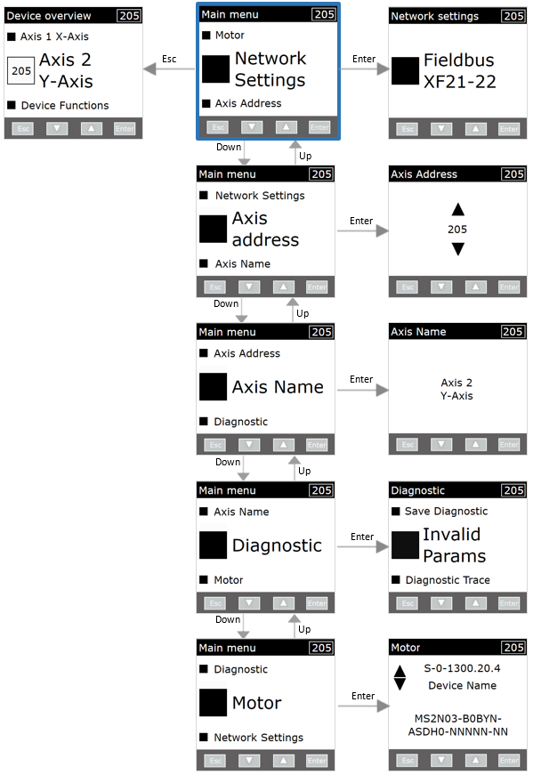
In the following you find an overview of the various operating levels.
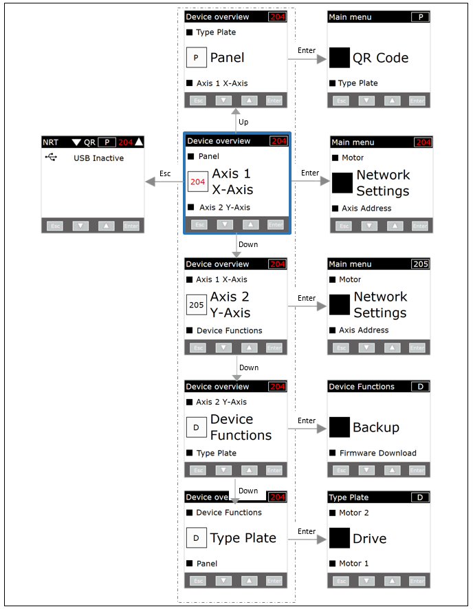
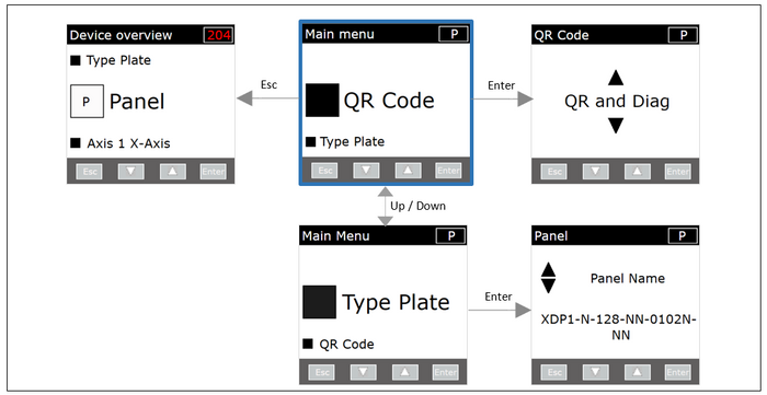
Device overview screen acts as a main screen through which user can navigate to any of the other menu screens.
2.1 Screen navigation
- In using the Up/Down/Enter buttons user can select different options available.
- You can jump directly to the Panel function by pressing Enter, if the P window is active!
- Or you have to select another window by use of the arrow keys.
- Panel --> To view & edit panel related configurations. This option is always available.
- Axis # --> To view & edit axis related configurations. This option is available when axis is connected.
- Device Functions --> To perform special operations at drive level.
- Type Plate --> To view the type plate details of Drive & Motors.
2.2 Overview
3. Device diagnostic screen
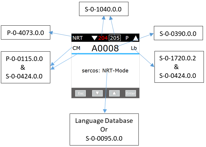
In here you see the data sources for each line or register.
Device diagnostic screen provides axis wise diagnostic information. Information displayed in this screen is read from axis through SIP request. For example the “communication diagnostic message”, or the “diagnostic message number”.
Information Source (related to drive parameters):
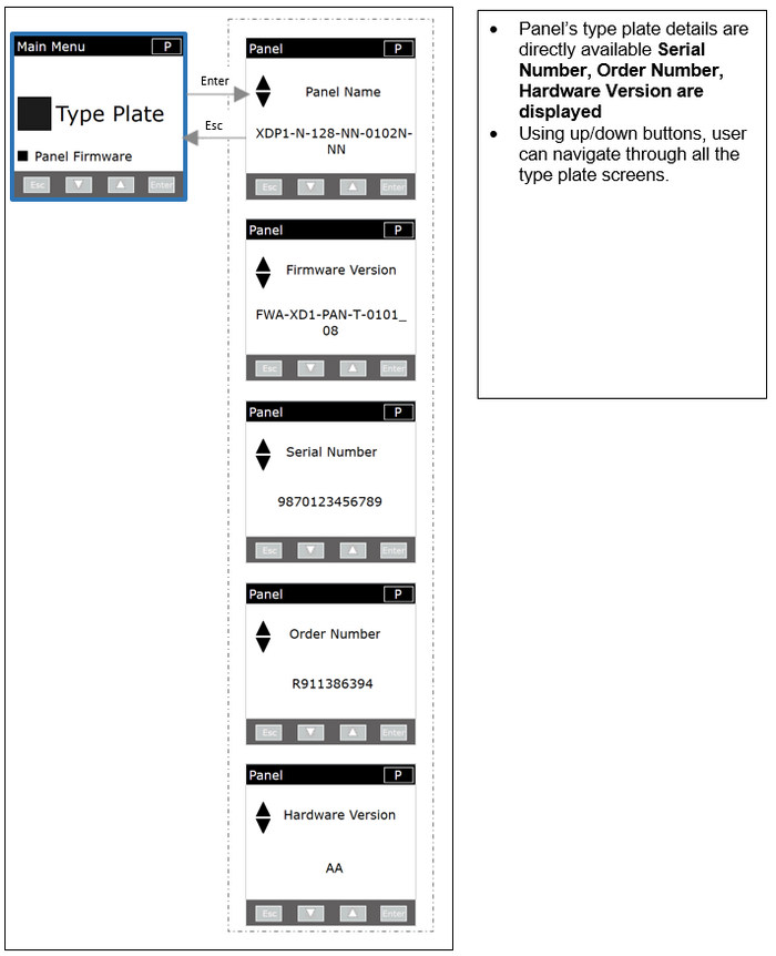
3.1 Panel Type Plate Screens
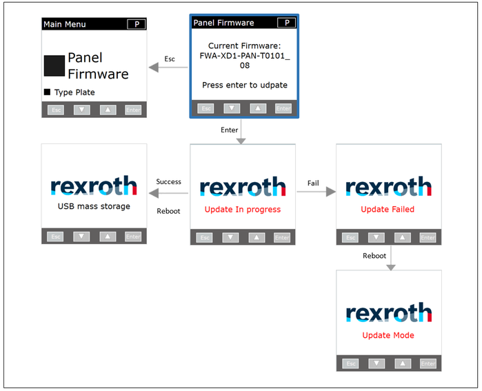
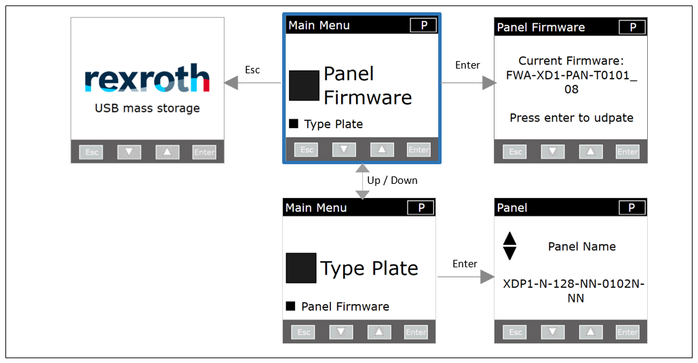
3.2 Panel Firmware Update Screen
- User can update the panel’s firmware in using this screen.
- It will show the panel’s current firmware details too. Upon confirmation firmware update process will start.
- User has to store the required latest firmware in panel’s flash memory.
- Folder path in panel’s flash memory:
F:\Panel\Firmware_update
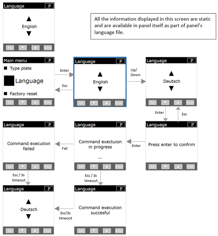
3.3 Panel Language Screens
- Using this screen, user can set the desired panel language.
- Current configuration shown upon initial screen display.
- Upon successful language setting, panel will restart in order to display the contents in selected language.
- All the supported language files available in panel’s mass storage will be shown as options in this screen. The list of languages which panel currently supports are English, German, French, Italian & Spanish.
- Below are the different language screens supported by panel
- Panel language selection screen (during first power ON)
- Panel language setting screen (part of panel main menu)
Note: This configuration should be stored in panel and retrieved in next power cycle.
3.4 Diagnostic Screen Overview
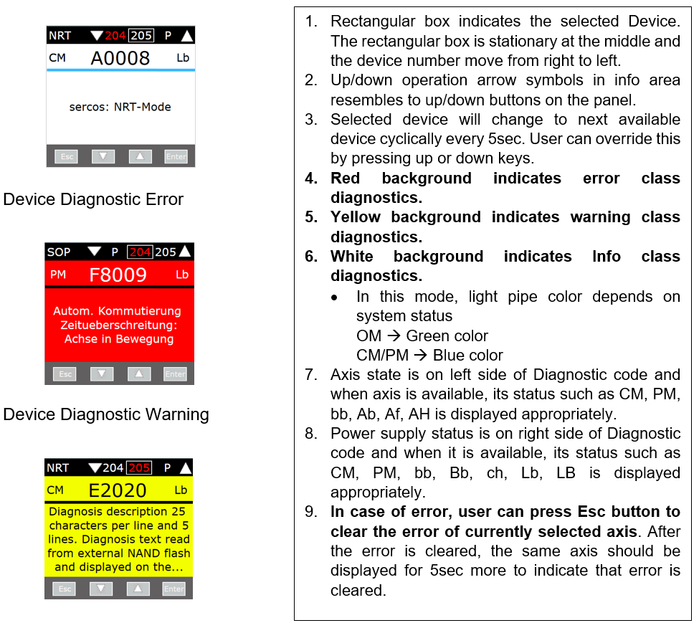
Diagnostic screen is used to display all the axis that are detected by panel. There are different types of diagnostic screens available, which are as mentioned below:
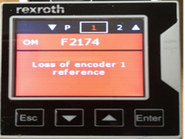
- Device Diagnostic Screen will display the diagnostic information of selected axis.
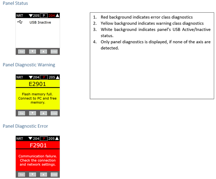
- Panel Diagnostic Screen will display the diagnostic information of panel itself.
QR Code will display the diagnostic information of all the axis that are detected.
Device diagnostic screen provides axis wise diagnostic information.
Information Source (related to drive parameters):
Depending upon the current diagnosis code, the appearance of screen differs. Different types of diagnostic codes are
- Information class diagnostic ranges from 0xA0000 to 0xAFFFF
- Warning class diagnostic ranges from 0xE0000 to 0xEFFFF
- Error class diagnostic ranges from 0xF0000 to 0xFFFFF
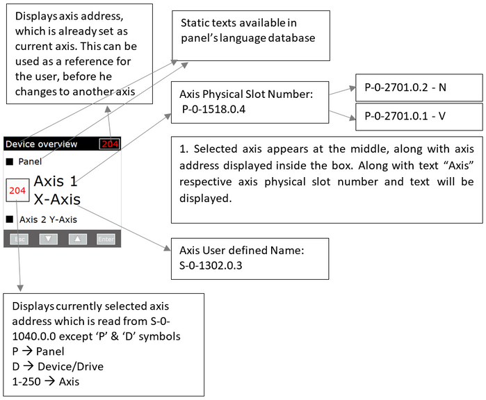
Sorting of axis is done by using the physical axis numbers which are read from
P-0-1518.0.4 --> P-0-2701.0.2 (N-V Parameters)
3.5 Device Diagnostic Info
3.6 Panel Diagnostic Screen
Panel diagnostic screen provides panel’s diagnostic information. Information displayed in this screen is provided from panel itself.
QR Code Diagnostic Screen
QR code diagnostic screen provides axis wise diagnostic information.
QR code diagnostic screen is configurable as per user requirement.
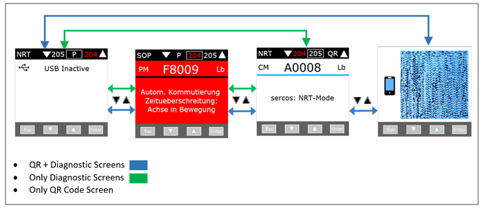
- QR + Diagnostic Screens (default selection)
- Only Diagnostic Screens
- Only QR Code Screen
3.7 Special Conditions
- In panel engineering mode, when there is no user activity in panel for 5minutes, then by default Diagnostic screen should be displayed.
- During screen transition, panel screen behavior is as mentioned below
0 to 5 secs --> Do nothing and wait for new screen to be displayed.
5 to 10 secs --> “Please wait” text to be displayed.
After 10 secs --> Jump to diagnostic screen. - In case of communication failure in “Only QR” code in panel engineering mode, there is no way to indicate user about presence of an error. In this case, QR scanned data contains only junk values or all the values will be set to 0, except the link to Bosch service app.
Diagnostic Screen Navigation
HMI events:
- Esc --> Clear error of currently selected axis, except QR code
- Down --> Navigate to previous axis
- Up --> Navigate to next axis
- Enter --> Display Device overview screen
Special events:
- If user has navigated to any other screen, then diagnostic screen will be displayed in the following conditions
- In case of error detection in any of the axis
- In case of no user activity for 5minutes
- If user navigates to any axis using up/down buttons, then the selected axis will be displayed for 60s and automatic inter-axis navigation will be resumed afterwards.
Automatic Inter-axis Navigation
Automatic switching is interrupted after selecting an axis.
Manual Inter-axis Navigation
Inter Screen Navigation
3.8 Priorities
Priorities with existing functionalities
- If user is performing any operation in other screens then user operation has higher priority and jumping to this screen will happen after 5mins of no user activity.
- Display of error screen is higher priority than display of confirmation screen.
- Display of confirmation screen is higher priority than display of warning screen. If warning occurs in parallel, then corresponding axis in info screen should indicate it.
- Stop the automatic axis navigation upon display of this screen.
- In “only QR” diagnostic screen, do not display axis identifier confirmation screen, as QR is for the device and SMO identifier confirmation is for only an axis.
- During confirmation, if axis is forced to PM/OM mode, panel will clear the confirmation message displayed (if already displayed) and it will display normal diagnostic screen data with PM/OM data. If axis comes back to CM mode and if parameter P-0-3235.0.4 = 0, panel will display the confirmation message again on the screen.
Operation in safe motion confirmation screen
- Using this screen user can confirm the safe motion identification. And user cannot cancel the confirm identifier message from the panel.
4. Panel Main menu Screen
Panel Main menu in Panel Engineering Mode
Panel Main menu in USB mass storage Mode
5. Axis Main menu Screen
Using this screen user can view all the configurations of axis, which are supported by panel.
6. Device Functions Menu Screen
- Device functions screen provides list of functionalities which can be performed on the entire device.
- Using Up/Down/Enter buttons user can select different options available.
- Backup --> To take backup of parameters into panel’s external flash memory.
- Firmware Download --> To download the new firmware to drive.
7. Device Type Plate Menu Screen
- Using this screen user can access the different Type Plate details that can be accessed from the entire device.
- Using Up/Down/Enter buttons user can select different options available
- Drive --> To view type plate details of drive
- Motor --> To view type plate details of motor connected respective axis
Example: Motor 1 corresponds to the motor which is connected to Axis 1
- Power Supply --> To view type plate details of power supply
Note: If connected device type is
“XVx” --> “Power Supply” option is displayed.
“XCx or XMx” --> “Drive” option is displayed.
8. Panel Factory Reset Screen
- Using this screen, user can reset the panel settings to its default values.
- Upon successful command execution, panel will restart.
Information Source
9. Backup and Restore
- Backup of maximum 5000 IDNs and parameter data size up to 64KB supported by panel.
- The backup process is always for complete device. Backup of individual axis not supported by panel.
- The maximum number of .par files inside “Backup” folder is limited to ten.
- Restore function has not yet been implemented!
Which means that currently new parameter sets can only be loaded via ctrlX DRIVE Engineering.


