- Subscribe to RSS Feed
- Mark as New
- Mark as Read
- Bookmark
- Subscribe
- Printer Friendly Page
- Report Inappropriate Content
In the following we show to you how to correctly Power ON and OFF ctrlX DRIVE.
All the functions and screen shots are based on:
- ctrlX DRIVE Engineering version 01V14
- Runtime / Firmware version of drive AXS-V0306 or
Runtime / Firmware version of drive AXS-V0210
1. Prerequisites
A connection to the ctrlX DRIVE has been successfully established, the device is correctly wired and 24 V are successfully put on. As well the engineering tool ctrlX DRIVE Engineering has been started.
2. Power ON/OFF with I/Os
2.1. Schematics for power supply discharged at Power OFF
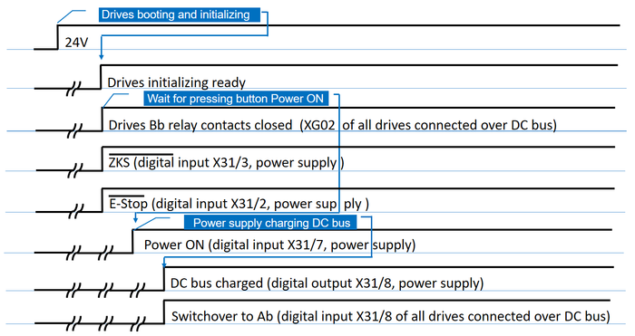
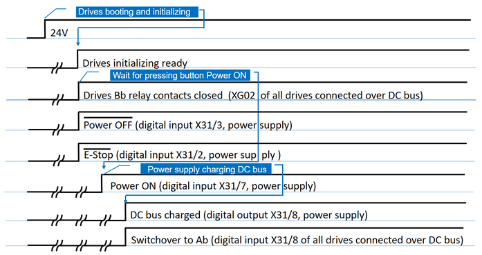
The power ON sequence of ctrlX DRIVE, if done via I/O wiring, follows the principle that
- the “ready” state of all drives connected over DC bus is collected over the Bb relays of all the axes
- that collected “ready” state powers on the power supply
- the power supply then tells the axes to change from “bb” to “Ab”
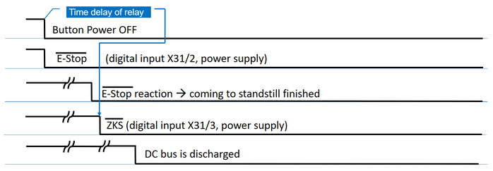
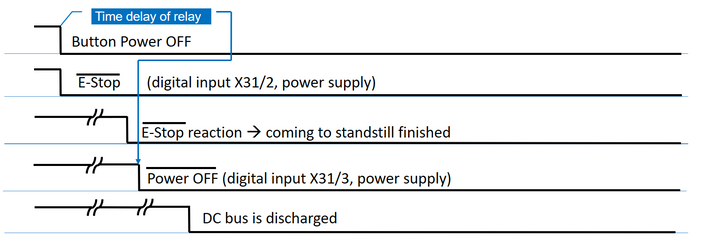
The overall sequences should be according to the following schematics if using the example wiring.
Fig. 1.: Overall sequence for Power ON over I/Os (acc. to example wiring)
Fig. 2.: Overall sequence for Power OFF over I/Os (acc. to example wiring)
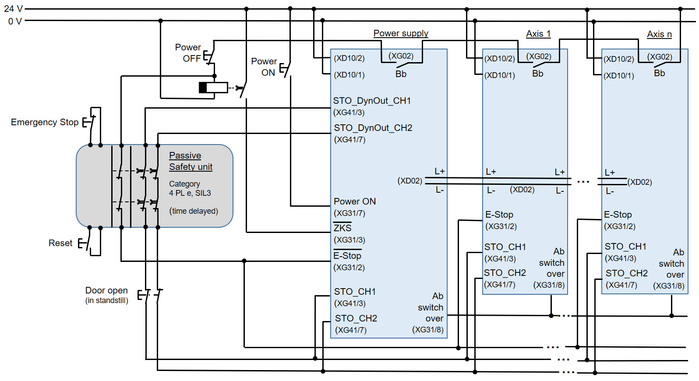
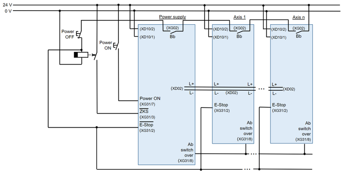
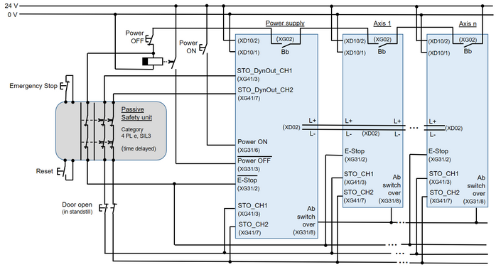
The overall electrical circuit should be looking like that.
Fig. 3.: Overall electrical circuit for power on over I/Os, if using drives with STO (Safe torque off) function (acc. to example wiring) and DC bus is discharged at Power OFF
Fig. 4.: Overall electrical circuit for power on over I/Os, if using drives with SMO (Safe Motion) function (acc. to example wiring) and DC bus is discharged at Power OFF
2.2. Parameterization of power supply (XVR, XVE, XCS, XCD) discharged at Power OFF
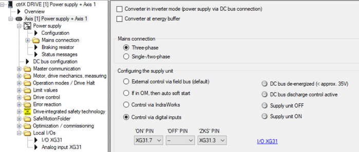
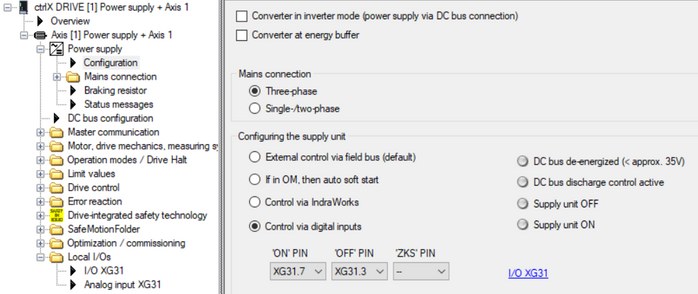
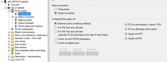
The power supply configuration needs to be set for three-phase or single-, two-phase connection depending on the installation. Select the “Control via digital inputs”! The pins are selected automatically if accordingly configured in the I/O configuration.
Fig. 5.: Power supply: Configuration (acc. to example wiring), DC bus is discharged at Power OFF
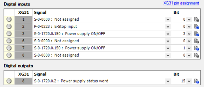
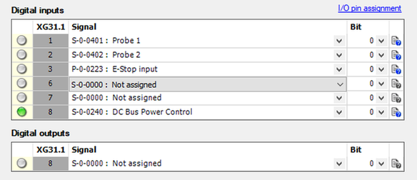
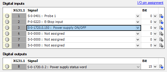
If pressing the link I/O XG31.1 you get to the I/O configuration. Select the signals as shown in here.
Fig. 6.: I/O configuration of power supply (acc. to example wiring) ), DC bus is discharged at Power OFF
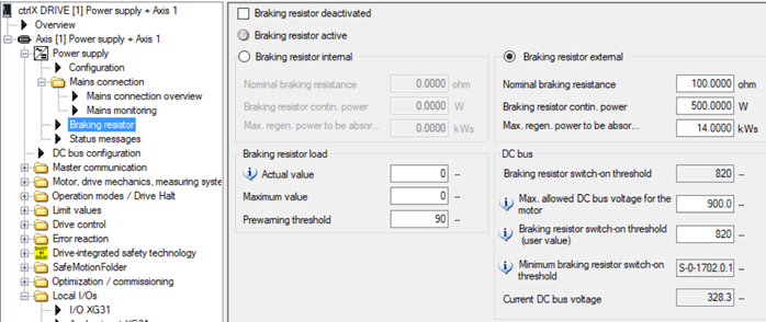
Fig. 7.: Mains connection: Braking resistor settings --> set parameters according to your application
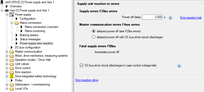
The power off delay time should match the maximum time needed for the deceleration of the axes with the longest deceleration time with some time margin.
Fig. 8.: Mains connection: Power supply error reaction --> set power off delay time according to your application
Fig. 9.: DC bus configuration of power supply --> set DC bus undervoltage threshold according to your application (standard setting is 200 V)
2.3. Schematics for power supply not discharged at Power OFF
The power ON sequence of ctrlX DRIVE, if done via I/O wiring, follows the principle that
- the “ready” state of all drives connected over DC bus is collected over the Bb relays of all the axes
- that collected “ready” state powers on the power supply
- the power supply then tells the axes to change from “bb” to “Ab”
The overall sequences should be according to the following schematics if using the example wiring.
Fig. 10.: Overall sequence for Power ON over I/Os (acc. to example wiring), DC bus is not discharged at Power OFF
Fig. 11.: Overall sequence for Power OFF over I/Os (acc. to example wiring), DC bus is not discharged at Power OFF
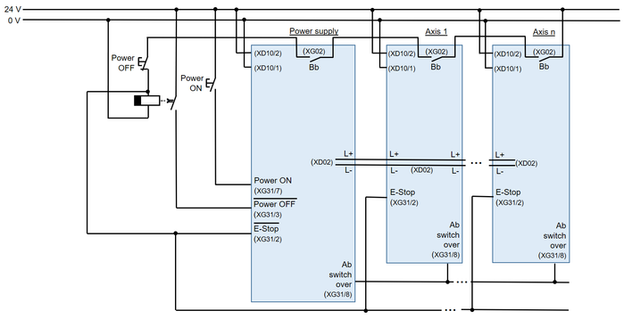
The overall electrical circuit should be looking like that.
Fig. 12.: Overall electrical circuit for power on over I/Os, if using drives with STO (Safe torque off) function (acc. to example wiring), DC bus is not discharged at Power OFF
Fig. 13.: Overall electrical circuit for power on over I/Os, if using drives with SMO (Safe Motion) function (acc. to example wiring), DC bus is not discharged at Power OFF
2.4. Parameterization of power supply (XVR, XVE, XCS, XCD) not discharged at Power OFF
The power supply configuration needs to be set for three-phase or single-, two-phase connection depending on the installation. Select the “Control via digital inputs”! The pins are selected automatically if accordingly configured in the I/O configuration.
Fig. 14.: Power supply: Configuration (acc. to example wiring), DC bus is not discharged at Power OFF
Rest of parameterization and configuration is done like shown before in chapter 2.2.
2.5. Parameterization of inverters (XMS, XMD)
In similar way the DC bus configuration of the inverters has to be set.
Mind that normally the DC bus undervoltage threshold should be set to the same value in all devices connected to the same DC bus.
Fig. 14.: DC bus configuration of axes à set DC bus undervoltage threshold according to your application (standard setting is 200 V)
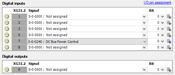
If pressing the link I/O XG31.1 you get to the I/O configuration. Select the signals as shown in here.
Fig. 15.: I/O configuration of inverters (acc. to example wiring)
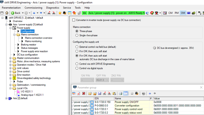
2.6. Variant: Automatic load of DC bus to power ON
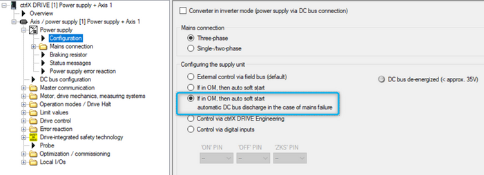
If selecting the configuration
- If in OM, then auto soft start
or
- If in OM, then auto soft start, automatic DC bus discharge in the case of mains failure
it is possible to keep the mains connected at all time.
This variant can also be used for operation via fieldbus connection. Then only the Power ON and OFF bits need to be used.
It is not necessary to control the parameters S-0-1720.0.150, S-0-1720.0.1 and S-0-1720.0.2 externally.
Fig. 16.: Power supply: if in OM, then auto soft start
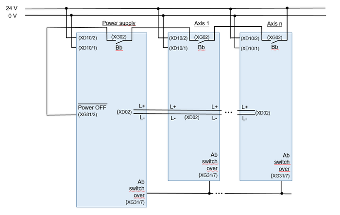
Minimal wiring is required for the exchange of information with other devices on the same DC bus.
Fig. 17.: Example wiring
I/O Assignment at the power supply XG31.
Fig. 18.: Example I/O assignment at power supply
I/O Assignment at the axes.
Fig. 19.: Example I/O assignment at axes
3. Power ON/OFF with fieldbus
3.1. Power supply state machine
The power on sequence of ctrlX DRIVE, if done via fieldbus, follows the principle that
- the power supply state machine is controlled by power supply control and status word (S-0-1720.0.1, S-0-1720.0.2)
In case of multi axes connected to DC bus:
- the “ready” state (bb) of all drives connected over DC bus is collected via device status word (P-0-0115 Bit 0) by fieldbus
Mind that the status information can also be exchanged via signal status word. See chapter 4.1. in this document.
- that collected “bb” states are used to decide when power ON can be triggered by control
- when power supply is ready (LB) this info is forwarded to all axes to switch to state “Ab” (S-0-0240)
Mind that the control bit can also be exchanged via signal status word. See chapter 4.1. in this document.
Note: If a power supply is present with multi axes integra-ted (i.e. XCD) the information is exchanged internally.
The principle wiring and schematic possibilities you can find in chapter 9.1.4 of ctrlX DRIVE Runtime application manual (R911398021)
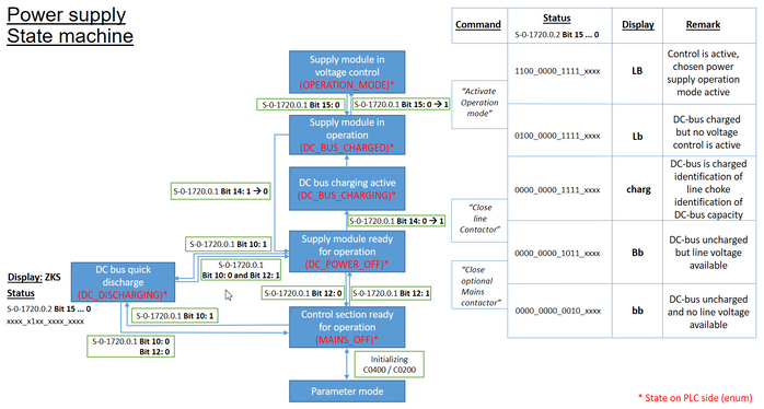
The power supply state machine illustrates the sequence you need to meet to switch on the supply. There is a function block for ctrlX CORE PLC to control the state machine.
For detailed info (also for other device types) see also chapter 4.2.3 of ctrlX DRIVE Runtime application manual.
Fig. 20.: Power supply state machine XCS/XCD/XVE
Relevant parameters:
- Power supply (XVE/XCS/XCD)
S-0-1720.0.1 (Alias S-0-2057) „Power supply control word“
S-0-1720.0.2 (Alias S-0-2058) „ Power supply status word “ - Inverter in axis group
S-0-0240 „DC Bus power control“
P-0-0115 „Device status word”
Mind: These parameters can also be mapped in signal control/status word.
3.2. Parameterization of power supply (XVR, XVE, XCS, XCD)
The power supply configuration needs to be set for three-phase or single-, two-phase connection depending on the installation. Select the “External control via fieldbus” to control power supply state machine via power supply control word!
Fig. 21.: Power supply: Configuration
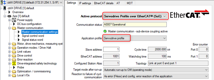
You need to activate a fieldbus protocol for communication.
For a combination with our ctrlX CORE you should use EtherCAT and Servodrive profile.
Fig. 22.: Fieldbus protocol and Servodrive profile
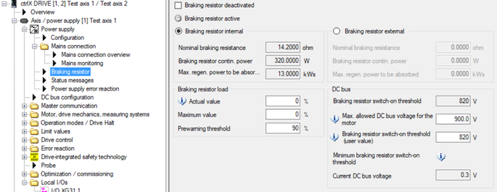
A breaking resistor is necessary in case you want to use ZKS (DC short circuit) to discharge the DC bus voltage.
Fig. 23.: Mains connection: Braking resistor settings à set parameters according to your application.
Fieldbus communication needs to be enabled in all connected axes as well. No other modifications are necessary.
3.3. Configure ctrlX CORE
The task of ctrlX CORE is to operate and evaluate the power supply control and status word. To do this, the information needs to be exchanged via the fieldbus.
Mind: Special for EtherCAT: the so called “Alias” parameters need to be used.
The control/status words can be addressed directly via the data layer from an app or via the PLC I/O image as soon as the devices have been configured in the EtherCAT master. (For control/status word assignment, see parameter description).
Steps:
- Install EtherCAT Master App on ctrlX CORE. Open ctrlX I/O Engineering and scan for devices!
- Add scanned devices to the project!
- For devices with power supply (XCS, XCD, XVE, XVR), the power supply control/status words are configured by default in the process data (MDT / AT).
Note: for power supply control/status words, “Alias” parameters are used depending on the fieldbus. - For inverters without power supply (e.g. XMS, XMD) supplied directly via the DC bus, the power control word (S-0-0240) and device status word are configured by default in process data (MDT/AT).
- If necessary, activate EoE, afterwards download and activate fieldbus configuration to ctrlX CORE!
- Read/write power supply control/status word from PLC side. Therefor install PLC app on ctrlX CORE and open ctrlX PLC Engineering.
- Scan configured process data under Realtime_Data node, which we had previously configured in ctrlX I/O Engineering.
- Power supply control/status word can be controlled directly via the process data. Alternatively, there are function blocks (Lib: CXA_Drive_Util) for ctrlX CORE to control the power supply state machine.
- In both cases, you need to map the power supply control/status word to a PLC variable. Create this variable in your program or global variable list in before. Mapping can also be done via addresses (%IW2,…), if variable is declared accordingly.
- In case of inverters (e.g. XMS, XMD) connected to DC bus, you need to map device status word and DC bus power control word to a variable as well.
- Add CXA_DriveUtil to library manager
Hint: You need to activate ‘display advanced libraries’
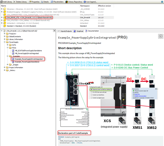
There is an example code available in the Examples folder.
Function block PowerSupplyDriveIntegrated is fieldbus independent and can be used for standalone power supplies as well.
Fig. 24.: Example code for MB_PowerSupplyDriveIntegrated function block
- Copy example code to your program and download it to ctrlX CORE!
When all connected axes report bb state, power supply will be switched to LB (= Operation_Mode) automatically after FB is activated by variable bEnablePower. When a single axis is not in bb, power supply will be switched to bb (Mains_Off_No_Discharge). You can change the target states or switching conditions according to your requirements.
4. Power ON/OFF with fieldbus using signal control and signal status word
4.1. Power supply state machine
The power on sequence of ctrlX DRIVE, if done via fieldbus, follows the principle that
- the power supply state machine is controlled by power supply control and status word (S-0-1720.0.1, S-0-1720.0.2)
In case of multi axes connected to DC bus:
- the “ready” state (bb) of all drives connected over DC bus is collected via device status word (P-0-0115 Bit 0) by fieldbus in signal status word.
- that collected “bb” states are used to decide when power ON can be triggered by control
- when power supply is ready (LB) this info is forwarded to all axes to switch to state “Ab” (S-0-0240) via signal control word.
Note: If a power supply is present with multi axes integrated (i.e. XCD) the information is exchanged internally.
The principle wiring and schematic possibilities you can find in chapter 9.1.4 of ctrlX DRIVE Runtime application manual (R911398021)
The power supply state machine illustrates the sequence you need to meet to switch on the supply. There is a function block for ctrlX CORE PLC to control the state machine.
For detailed info (also for other device types) see also chapter 4.2.3 of ctrlX DRIVE Runtime application manual.
Relevant parameters:
- Power supply (XVE/XCS/XCD)
S-0-1720.0.1 (Alias S-0-2057) „Power supply control word“
S-0-1720.0.2 (Alias S-0-2058) „ Power supply status word “
- Inverter in axis group
S-0-0240 „DC Bus power control“
P-0-0115 „Device status word”
These parameters need to be mapped in signal control/status word
4.2. Parameterization of power supply (XVR, XVE, XCS, XCD)
See chapter 3.2 for basic settings.
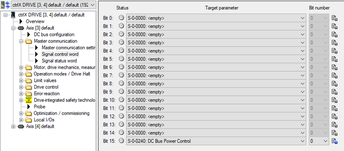
For using signal control/status word, you have to configure the necessary bits.
Fig. 25.: Configuration of signal control word in power supply. Don´t configure in XCD or XCS axis!
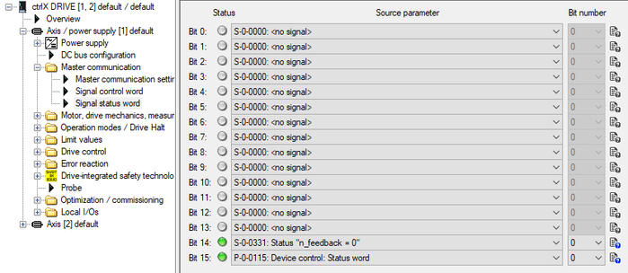
Fig. 26.: Configuration of signal status word
Fieldbus communication need to be enabled in inverters (e.g. XMS, XMD) as well.
4.3. Configure ctrlX CORE
The task of ctrlX CORE is to operate and evaluate the power supply control and status word. To do this, they need to be exchanged via the fieldbus.
Mind: Special for EtherCAT: the so called “Alias” parameters need to be used.
The control/status words can be addressed directly via the data layer from an app or via the PLC I/O image as soon as the devices have been configured in the EtherCAT master. (For control/status word assignment, see parameter description).
For devices with power supply (XCS, XCD, XVE, XVR), the power supply control/status words are configured by default in the process data (MDT / AT). You have to add signal control word (S-0-0145) and signal status word (S-0-0144).
Note: For power supply control/status words, alias parameters are used depending on the fieldbus!
Fig. 27.: Cyclic data (MDT/AT) of power supply (e.g. XCS, XCD axis 1)
For slave axis of XCD or modular inverters (without power supply, XMS, XMD) supplied directly by DC bus, signal control word (S-0-0145) and signal status word(S-0-0144) have to be added in process data (MDT/AT).
Fig. 28.: Cyclic data (MDT/AT) of inverter (e.g. XMD, XMS)
4.4. Example for a power supply function block
In the following chapter, you get an example of creating a function block, which you can call from your PLC Main Program.
Steps:
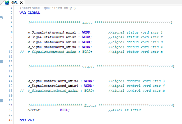
Add variables in global variable list!
Fig. 29.: Sample code for global variables
Get information about status of connected axes on DC Bus!
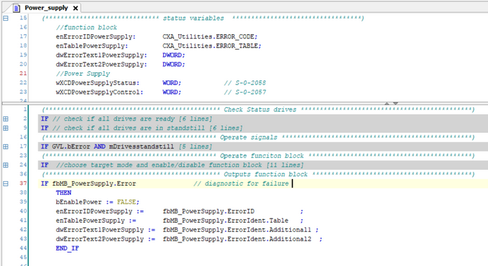
Fig. 30.: Sample code for checking drive status “bb” and “Standstill”
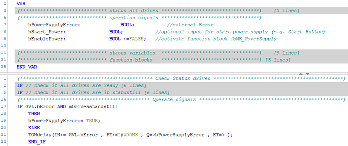
Check if an external error is present, which needs to power off the machine. If there is an error present and the drives are not in “Standstill” use a delay block to allow the stopping of the moving axes.
Fig. 33.: Sample code for check of external errors
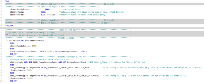
When axes are ready and no error is signaled, target mode “LB” of the power supply should be chosen, then the bit for enabling the function block should be set. Otherwise the Power has to be shut down.
You may add a bit (e.g. for handling an external button) for “Power ON”.
Fig. 34.: Sample code “Power On” or “Power OFF”
Add failure diagnostic for better analysis of error states. Disable the power supply when an error occurs.
Fig. 35.: Sample code for failure diagnostic
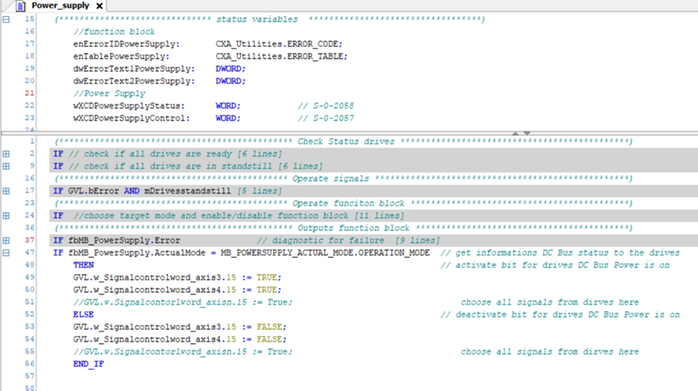
If the power supply is in target mode “LB”, activate the following bits on the inverters (e.g. XMS, XMD).
Fig. 36.: Sample code if power supply is in “LB”
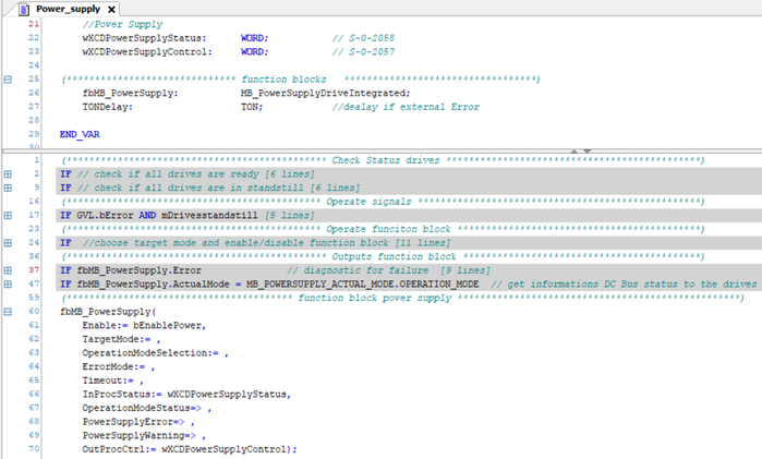
Finally map your variables to the function block!
Fig. 37.: Sample code function block MB_PowerSupply
5. Power ON/OFF using IndraMotion MTX or MLC
5.1. Timing sequence schematics
The power ON sequence of ctrlX DRIVE, if using IndraMotion MTX or MLC, follows the principle that
- the “ready” state of all drives connected over DC bus is collected over the “bb” and “Ab” information already present in the status information of the control system for all axes --> only when the status of all axes is telling “Ab” then the control may set the drive enable signal to all drives.
- the power supply is automatically charging the DC bus and all axes automatically change from state “bb” to “Ab” if the DC bus is charged.
- the power supply unit can stay at always mains connected if machine is switched on and thus 24 V are supplied.
The overall sequences should be according to the following schematics.
Fig. 38.: Overall sequence for Power ON over IndraMotion MTX or MLC
* NC-PLC interface "iAx_DrvReady" at IndraMotion MTX
** Structure "AxisData[Drive1.AxisNo].Axis_InAb" at IndraMotion MLC
Fig. 39.: Overall sequence for Power OFF over IndraMotion MTX or MLC
* NC-PLC interface "iAx_DrvAct" at IndraMotion MTX
** Structure "AxisData[Drive1.AxisNo].Axis_Power" at IndraMotion MLC
5.2. Parameterization of power supply (XVR, XVE, XCS, XCD)
The power supply configuration needs to be set for three-phase or single-, two-phase connection depending on the installation.
Fig. 40.: Power supply: Configuration
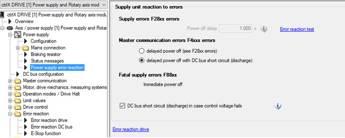
Fig. 41.: Mains connection: Power supply error reaction --> set delayed power off with DC bus short circuit (discharge) --> then after the set 1s delay time the DC bus is discharged
5.3. Parameterization of inverters (XMS, XMD)
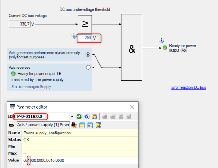
In similar way after setting Bit 15 = “1” in parameter P-0-0118 the DC bus configuration of the inverters has to be set.
Mind that normally the DC bus undervoltage threshold should be set to the same value in all devices connected to the same DC bus.
Fig. 42.: DC bus configuration of axes --> set DC bus undervoltage threshold according to your application (standard setting is 200 V)
Mind: The remark “(only for test purposes)” can be neglected in the use cases with IndraMotion MTX and MLC.
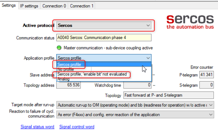
Fig. 43.: Master communication settings --> Sercos as active protocol and one of the Sercos profiles must be selected
You must be a registered user to add a comment. If you've already registered, sign in. Otherwise, register and sign in.


