
- Subscribe to RSS Feed
- Mark as New
- Mark as Read
- Bookmark
- Subscribe
- Printer Friendly Page
- Report Inappropriate Content
In the following we show to you how to configure a DC/DC-converter XMV02.
Versions used
All the functions and screen shots are based on:
- ctrlX DRIVE Engineering version 01V16
- Runtime / Firmware version of drive AXS-V0308
Pre-requisites
A connection to the ctrlX DRIVE has been successfully establi-shed, the device is correctly wired and 24 V are successfully put on. As well the engineering tool ctrlX DRIVE Engineering has been started.
1. Field of use and application
The XMV02 is a DC/DC-converter. It converts a DC voltage into a DC voltage of a different value.
- Step-down converter --> UDC,out < UDC,in
- XMV02 can be operated voltage- and current-controlled
- Feed-in and regenerative operation are possible

Fig. 1.: DC-converter system structure
Detailed information on the system structure can be found in the following documents:
- R911413650 English application description
- R911413649 German application description
2. Parameterization
2.1. Analog input
For operation mode voltage control, an external measuring transducer is needed. This converts the output DC voltage into a measuring signal 0 ... 10 V.
Parameter S-0-1742.0.160 DC voltage feedback value is configured as target parameter in the analog input.
The nominal value P-0-2900.0.3 has to be set to the range of the measuring transducer.
In the following case, the transducer has a measuring range of 0-750V, which is converted to 0-10V.

Fig. 2.: Dialog analog input - example parameterization
2.2. DC bus configuration
The DC/DC-converter requires the “ready for operation” signal from the power supply unit, which provides the DC-bus. This signal can be written via master communication or set to a digital input that transmits the status to S-0-0240 bit 0.
For DC-bus undervoltage threshold parameter S-0-1741.0.160 direct voltage command value is used.
--> Also when operating in current control it is recommended to write a value to S-0-1741.0.160 to use the DC-bus undervoltage threshold.

Fig. 3.: DC-bus configuration
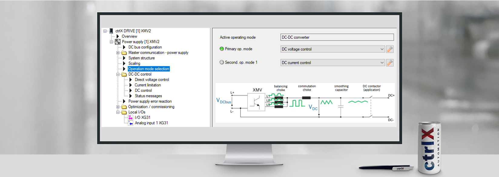
2.3. Operation modes and control loop
There are two operation modes available in the DC/DC-converter. Per default, DC voltage control is set as primary operation mode and DC current control as secondary operation mode.
The operation modes can be set depending of the application.

Fig. 4.: Operation mode selection
DC-voltage control:
A voltage command value is written to the DC/DC controller (from a higher-level controller) via parameter S-0-1741.0.160. “DC- voltage command value". The DC output voltage is controlled. The control loop design is using a cascade control. This means that the voltage control gives a current command value to the subordinate current control.

Fig. 5.: DC voltage control
DC-current control:
A current command value is written to the DC/DC controller (from a higher-level controller) via parameter "S-0-1741.0.161" “DC current command value”. The DC output current is controlled

Fig. 6.: DC current control
2.4. Limitations
Power limitation (New feature compared to IndraDrive ML)
In order to limit the energy taken from the DC bus or fed back into the DC bus, limit values can be set.
If the product of the output voltage and the output current (actual values) exceeds the limits set here, the current is reduced accordingly.
The power limit should not be used for power control, as the control loop is not designed for this purpose. In case of active power limitation the voltage and current ripple may increase.
The power limitation only works with correct voltage feedback.
The power limitation should be adjusted to the DC link voltage.
Involved parameters
S-0-1741.0.187 Power limit value positive
S-0-1741.0.188 Power limit value negative
S-0-1742.0.163 Output power actual value
Current limitation
The output current can be limited in amplitude via the DC current limits.
This is necessary if the external components (e.g. smoothing choke) cannot carry the full device current or the connected load requires this.

Fig. 7.: Dialog current limitation
The following evaluation applies:
"S-0-1701.0.1 Rated current supplier" correspond to 100% / √2 = 70.7% of the single phase current.
The current is limited per phase à output current = 3 × phase current.
Example:
Rated utility current = 18 A per phase Þ 18 A × 3 = 54 A.
Limitation to ±50 A:
DC current limit bipolar = (50 A / 18 A) × 70.7% = 196.4%.
Involved parameters
S-0-1741.0.180 DC current limit bipolar
S-0-1741.0.181 Positive DC current limit value
S-0-1741.0.182 DC current limit value negative
S-0-1701.0.1 Nominal current of power supply
DC current controller output limitation
In order to limit the output voltage in the event of a fault (e.g. failure of the external voltage measurement), it is possible to limit the setting range of the step-down converter and thus the maximum possible output voltage.
For this purpose, the max. DC voltage can be entered in parameter S-0-1741.0.186.
With the output limiting the output voltage is caused by a limitation of the PWM duty cycle. This means that in the case of limitation a fixed PWM is set. This means that when a higher voltage is applied to the DC output, no control of the DC current is possible.
In this case an overload shutdown of the power unit occurs.
Note: Depending on the current direction, output current and switching frequency, a deviation of +-50V is possible.
Involved parameter
S-0-1741.0.186, DC current controller output limitation
3. Power ON/OFF
3.1. DC/DC converter state machine

Fig. 8.: State machine of DC/DC-converter
Control and status words of the DC/DC converter state machine
- S-0-1720.0.1, Power supply control word Alias parameter: P‑0‑2714, Power supply control word
- S-0-1720.0.2, Power supply status word Alias parameter: P‑0‑2715, Power supply status word
3.2. Switch on sequence
With “Softstart” (S-0-1741.0.150 = 0000.0000.0000.0000):
According to the state machine, a switch on is carried out to the following pattern:
|
status |
S-0-1720.0.1 Supplier control word |
|
“bb” |
0x0000 |
|
“Bb” |
0x1000 |
|
“LB” |
0x5000 |
|
“LF” |
0xD000 |
0x5000 is in principle using the operating mode DC voltage control. The voltage command value is regulated with 1/10 device peak current.
It is also possible to switch directly between voltage and current control: 0xD000 à 0xD100 switches dynamically between main operating mode and secondary operating mode.
Without “Softstart” (S-0-1741.0.150 = 0000.0000.0000.0001):
Here the "Softstart" (0x5000) is skipped. This has the following advantages:
- You can go directly from "Bb" to "AF". This is important if you want / have to go directly into current control (e.g. pure current source) without having to take a detour via voltage control
- It is possible to switch between the operating modes with the power amplifier inactive:
|
Step 1 |
Step 2 |
Step 3 |
|
0x9000 |
0x1000 |
0x9100 |
|
DC-voltage control “LF” |
Output stage disabled “Bb” |
DC-current control “LF” |
According to the state machine, a switch on is carried out to the following pattern:
|
status |
S-0-1720.0.1 Supplier control word |
|
“bb” |
0x0000 |
|
“Bb” |
0x1000 |
|
“LF” |
0x9000 |
Example:
You want to charge a battery, which is connected via a contactor. So first the output voltage is set (0x9000 electrolytic capacitors charge to battery level), then the output voltage is switched off (0x1000 output voltage remains stable), the contactor is switched on and then the output stages are switched to current control (0x9100). If the output stages were not switched off, but switched directly to current control, the following would happen (depending on the time and duration of the switchover):
- Voltage control is still active, if contactor is already closed: Small voltage differences between battery and electrolytic capacitors lead to large currents, battery and DC-DC controller work against each other
- Current control is already active when contactor is not yet closed: even at command value 0, a small current (ripple) flows, which inevitably charges or discharges the electrolytic capacitors. When the contactor is closed, a (large) voltage difference between the electrolytic capacitors and the battery could lead to large equalizing currents.

You must be a registered user to add a comment. If you've already registered, sign in. Otherwise, register and sign in.