
- Subscribe to RSS Feed
- Mark as New
- Mark as Read
- Bookmark
- Subscribe
- Printer Friendly Page
- Report Inappropriate Content
In the following we show to you how to commission the spindle positioning function via the ctrlX DRIVE Engineering tool.
Pre-requisites
All the functions and screen shots are based on:
- Runtime / Firmware version of drive AXS-V0306
- ctrlX DRIVE Engineering Version 03V14
A connection to the ctrlX DRIVE has been successfully establi-shed and the device is successfully powered on. As well the engineering tool ctrlX DRIVE Engineering has been started.
Purpose/Use of the function
The spindle positioning allows a oriented stop at a dedicated position of an axis or a spindle whilst running in velocity or torque control.
Commissioning sequence
First inside the so called "Productivity package" the firmware function for "Spindle positioning mode" needs to be enabled.

Fig. 1.: Enable "Spindle positioning mode" functionality
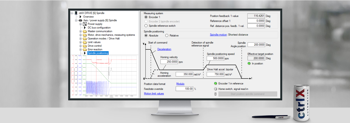
The dialog for setting the spindle positioning parameters itself looks like the following:

Fig. 2.: Spindle positioning parameters
It is recommended to first evaluate what the maximum possible deceleration of the spindle/axis is. This deceleration is set to parameter "Drive Halt accel. bipolar". The homing acceleration to around half this value.
The "Spindle positioning speed" [rpm] should be set to around: 0,8 * Sqr( 1800 * deceleration [rad/s^2] / PI())
In here: 0,8 * Sqr (1800 * 750 / PI()) = 524 rpm --> therefor 500 rpm was chosen
The "Homing velocity" is set to half the value, in here 250 rpm.
In clicking on the link "Spindle motion" further parameters are getting visible:

Fig. 3.: Further parameters are getting visible in clicking on "Spindle motion" link

Fig. 4.: Extended parameters for spindle positioning
Normally the recommendation is to select "Shortest distance", to activate the check box "Positioning velocity threshold active" and set the "Velocity threshold" around 20 rpm higher than the "Spindle positioning speed".
After setting the parameters in this way the functionality may be checked in performing a typical spindle positioning just drive based.

Fig. 5.: Start to command a usual spindle speed (in here 5000 rpm)
Then enter the intended "Spindle Angle position" and start the spindle positioning by hitting the button "Start position spindle command".

Fig. 6.: Test of spindle positioning function
Mind that the Spindle positioning can be executed absolute or relative. The corresponding radio button needs to be checked.
The spindle positioning should be looking similar to the following scope reading:

Fig. 7.: Typical scope reading of spindle positioning function (performed correctly): at around time 500 ms the spindle position speed of 500 rpm is reached and then the positioning takes place to target position 200° with nearly no additional time consumed

Fig. 8.: Typical scope reading of spindle positioning function (performed correctly)(Zoom on position) --> no overshoot is taking place

Fig. 9.: Typical scope reading of spindle positioning function (performed correctly): at around time 500 ms the spindle position speed of 500 rpm is reached and then the positioning takes place to target position 200° with some additional time consumed in order to get to target position on shortest distance

Fig. 10.: Scope reading if "Velocity threshold" is set to "0": Overshoot and change of direction is occuring
Last but not least the behavior if doing the spindle position starting from standstill should be checked as well.

Fig. 11.: Typical scope reading of spindle positioning function started from standstill (performed correctly)

Fig. 12.: Typical scope reading of spindle positioning function started from standstill (performed correctly)(Zoom on position) --> no overshoot occuring
Now the function may be called from the control system by using the direct parameter S-0-0152 and setting bits 0 and 1 on "1"

Fig. 13.: Spindle positioning command parameter
Mind that this parameter may be mapped to the parameter S-0-0145 (signal control word) and executed by setting the relevant bits.

You must be a registered user to add a comment. If you've already registered, sign in. Otherwise, register and sign in.