
- Subscribe to RSS Feed
- Mark as New
- Mark as Read
- Bookmark
- Subscribe
- Printer Friendly Page
- Report Inappropriate Content

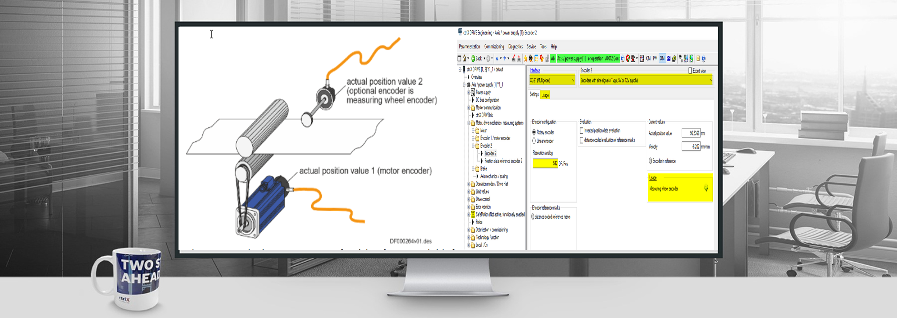
This picture describes the use of the measuring wheel function quite well. If the measuring wheel is in contact with the material, the function must be activated in parameter S-0-0520. If there is no contact between the measuring wheel and the material, then material feed should be carried out via the motor encoder, measuring wheel function itself then is deactivated via parameter S-0-0520. So the motor encoder is used for the positioning when you have no contact of the measuring wheel to the material.
Measuring wheel function - Prerequisites
The following prerequisites are required to use the function :
- ctrlX DRIVE Runtime >= AXS-V-0316
The following firmware functions must be enabled in order to use the measuring wheel function:
- Hybrid position control
- Measuring wheel mode

It also must be possible to connect a measuring wheel encoder to an interface on the drive control unit:
- Interface for Encoder 2
Measuring wheel function - Test equipment
I have taken the following measurements and pictures with the listed equipment:
Here is a picture of the experimental setup. As a coupling a rubber ring is used. The rubber ring simulates the material feed. The rubber ring is a very elastic connection. But for the demonstration here quite suitable. Real measuring wheel applications should be much stiffer.

Measuring wheel function - Parameterization
- Drive using the motor encoder has already been put into operation
- Now the measuring wheel mode will be parameterized


Measuring wheel function – Axis mechanics / scaling
If you have done the settings for the measuring wheel encoder then you can select the window „Axis mechanics / scaling“ and you have a good overview about your parameter settings.

Measuring wheel function - Drive controlled positioning (example)
Where to find the setting for the parameterization of the filter function:
If you go to your operation mode (here for example the Drive controlled positioning. Then select measuring wheel mode (hybrid position control). Then you see the window “Hybrid position control”.

Measuring wheel function – Involved parameters
The following parameters are used to parameterize the function
- S‑0‑0520, Axis control word
- S‑0‑0521, Axis status word
- P‑0‑0241, Actual pos. smoothing time constant for hybrid pos. control
- P‑0‑0242, Current actual slip value
- P‑0‑0243, Maximum occurred actual slip value
- P‑0‑0244, Monitoring window of slip
The following parameters are used to parameterize the measuring wheel encoder itself:
- S‑0‑0115, Encoder 2, type of position encoder
- P‑0‑0123, Encoder 2 feed constant
- P‑0‑0124, Encoder 2 gearbox revolutions, mechanical side
- P‑0‑0125, Encoder 2 gearbox revolutions, encoder side
- P‑0‑0185, Encoder 2 control word
Attachment: MeasuringWheelWatchList.jpg as a *.zip to open in ctrlX Drive Engineering
Measuring wheel function - Slip monitoring
Monitoring the slip
- Due to the measuring wheel mode, slip that can occur between material and drive motor is compensated via the position control. But slip also implies wear in the mechanical drive system and at the material. The controller supports reducing wear by allowing the occurring slip to be monitored with regard to a maximum allowed value to be set.
-
The current actual slip value is displayed in "P‑0‑0242, Current actual slip value". It refers to one measuring wheel revolution, if the "feed constant 2" is active in P‑0‑0185 (typical case: measuring wheel is measuring linear infeed) - or - one revolution of the external encoder, if "feed constant 2" is not active in P‑0‑0185 (encoder is measuring rotary infeed).
-
If the calculated slip exceeds the value in "P‑0‑0244, Monitoring window of slip" (value unequal "0"), the slip monitoring function triggers with the error message "F2036 Excessive position feedback difference" and the drive reacts with the error reaction that has been set.
- To determine the monitoring window, the maximum occurring slip, e.g. during a machining cycle, is stored in "P‑0‑0243, Maximum occurred actual slip value".
Measuring wheel function - Slip monitoring / current actual slip value

Measuring wheel function – Measurements
Here is a measurement with no active measuring wheel function on the test equipmet. Blue is the actual position value encoder1 and green is the command position value. Violet is the actual position encoder1.


Measuring wheel function - Hybrid position control – Control word control loop

Hybrid position control – Filter time constant
In the following some measurements are shown for a better understanding of the function and the oszilloscope data files have been added to the screenshots. If you want, you can take a closer look at the signals with the oscilloscope function. That's why the oscilloscope files are attached to the screenshots.


Related Links

You must be a registered user to add a comment. If you've already registered, sign in. Otherwise, register and sign in.