
- Subscribe to RSS Feed
- Mark as New
- Mark as Read
- Bookmark
- Subscribe
- Printer Friendly Page
- Report Inappropriate Content
Introduction
This documentation describes how to install and use ctrlX G-Code UI. G-Code UI was developed with Node-RED and PLC Engineering. It consists of a PLC project package and Node-RED template which can be customized.
G-Code UI functionality
G-Code UI supports the following features:
- Editor to create / write / delete a NC program
- NC program selection
- Start, stop, reset, and pause the NC program kinematics, respectively.
- Control path velocity by feedrate override
- Different coordinate systems like ACS and PCS
- Observe position and state of kinematics.
- System diagnostics
Installation and activation of G-Code UI
A licensed installation of following apps (V2.4.x or V2.6.x) is expected before activating G-Code UI.
Mandatory:
- ctrlX CORE - MOTION App (2.4.2 or V2.6.0)
- ctrlX CORE - Motion Standard License 4 Axes
- ctrlX CORE - Motion Cartesian License (add-on)
- ctrlX AUTOMATION - G-Code Runtime App (2.4.0 or V2.6.0)
- ctrlX OS License - G-Code Runtime
- ctrlX AUTOMATION - Node-RED App (2.4.0 or V2.6.0)
- ctrlX OS License - Node-RED
- ctrlX OS License - Node-RED
- ctrlX AUTOMATION - PLC App (2.4.0 or V2.6.0)
- ctrlX CORE License - PLC Standard (add-on)
- ctrlX AUTOMATION - G-Code UI (2.4.0)
- ctrlX AUTOMATION - G-Code UI (2.6.0.3)
Note: Please install G-Code Runtime App after MOTION App!
Optional:
- ctrlX AUTOMATION - 3D Viewer App
- ctrlX OS License - 3D Viewer
- ctrlX AUTOMATION - Oscilloscope App
The G-Code UI template includes two parts:
- PLC package: Bosch Rexroth AG GCode ****.package
- Node-RED template flows: GCode_UI_****.json (or GCode_UI_*.*.*.*.zip)
Both should be installed to activate and operate the UI.
PLC Part
Install the G-Code template package to the ctrlX PLC Engineering, only need to install for the first time:

 Select and insert G-Code template
 Select and insert Motion Interface template
 Application of PLC runtime in ctrlX WORKS is in state of RUN
 PLC interface variables in the DataLayer node
Node-RED part
There are two methods to load and active Node-RED configuration:
- Load GCode_UI_****.zip from the "Manage app data".
- Or import GCode_UI_****. json in Node-RED flow editor.
Note:
GCode_UI_****. json: It only contains the configuration of Node-RED, the user needs to add axes and create at least one kinematics before implementation.
- Switch ctrlX CORE state to "Setup" mode, uploads GCode_UI_****.zip file via "Home → Manage app data → Archive/Uploads Configuration".
- Active the configuration and switch the ctrlX CORE state to "Operating" mode.
 Activate the configuration of Node-RED by loading the GCode_UI_****.zip file
 Activate the configuration of Node-RED by import the GCode_UI_****. json file
 “Data Layer Request” node
 “Data Layer Subscribe" node
How to log in “Data Layer Request” node:
- Double-click any “Data Layer Request” node to open the configuration window.
- Enter the user name and password to log in, as shown in the figure below.
- Deploy the flows.
 How to log in Data Layer request node
Description of G-Code UI
G-Code UI have two mode: HMI-Configuration and HMI-Operating.

HMI-Configuration is shown as picture. Before you switch from UI to operating mode, it is needed to refresh and select the right kinematics. The table 1 describes the areas in configuration mode:
| Name | Description | |
| 1 | Select option | Select kinematics to be activated from the "Select option" drop-down menu. |
| 2 | REFRESH | Load all of kinematics which have been created in motion kernel. |
| 3 | OPERATING | Switch HMI mode from configuration to operating. |
| 4 | Selected kin | Displays the loaded kinematics. |
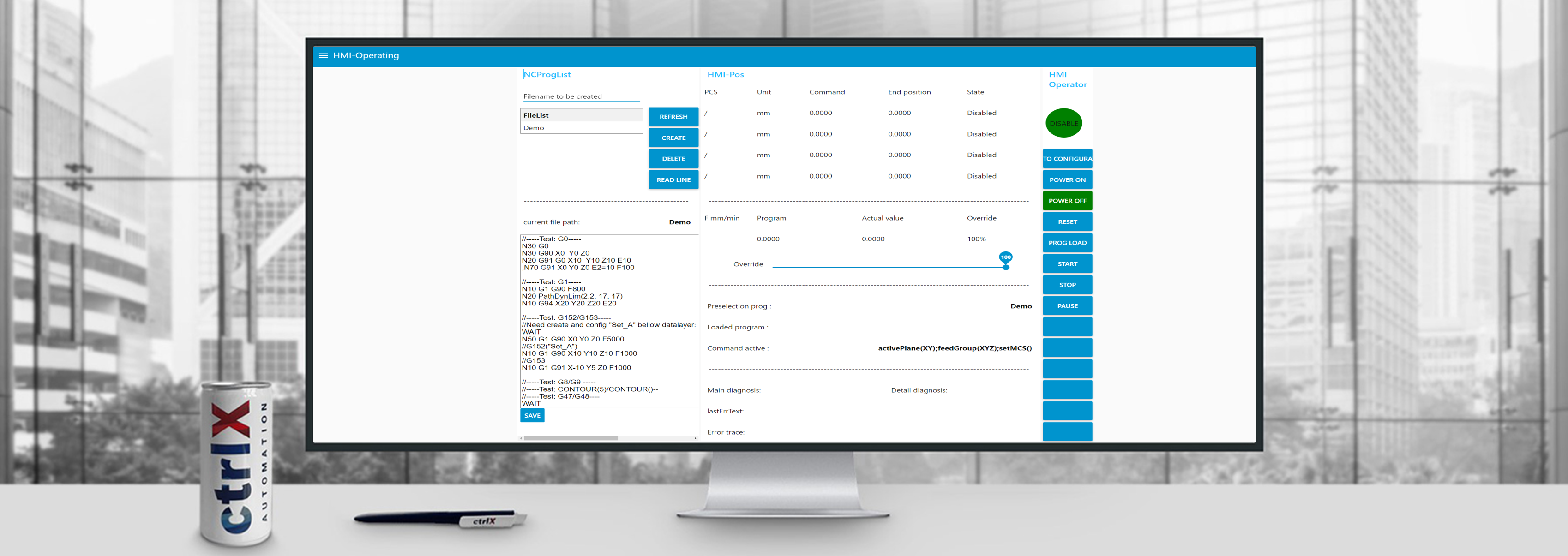
HMI-Operating of UI includes four areas: program, machine status, operation and diagnosis.

Program area:
| Name | Description | |
| 1 | File List | Show the list of NC programs. The default storage path is "Manage app data/Active/scripts/gcode". |
| 2 | Filename to be created | Input the name of new NC program. |
| 3 | REFRESH | Refresh the NC program list. |
| 4 | CREATE | After input the new program name via "Filename to be created", click "CREATE" to create program. |
| 5 | DELETE | Delete program. |
| 6 | ACTIVE BLOCKS | Switch page to "ACTIVE BLOCKS" manually. Only when NC program is running, the "ACTIVE_NC_ BLOCKS" page can display the executing NC blocks. Switch from "Active_NC_Blocks" page to "NC_Program" page via "PROGRAM" button. |
| 7 | SAVE | Save the NC program. |
Machine status area:
- Display axis status, position, and velocity information. Maximal four axes status can be displayed.
- Slider of override to modify the percentage of command value F.
- Observe the active command options.
- Show kinematics activated name and state.
- Displays pre-selected and loaded programs.
Operating area:
This area provides operation buttons to control the system.| Name | Description | |
| 1 | CONFIGURATING | Switch HMI from operating to configurating. |
| 2 | KIN ON | Axes power on and group enable. |
| 3 | KIN OFF | Axes power off and group disable. |
| 4 | PROG LOAD | Load the pre-selected program, switch UI state from "DISABLED" to "READY". |
| 5 | START |
|
| 6 | STOP | Stop NC program, switch UI state from "RUNNING" /"PAUSE" to "READY". |
| 7 | PAUSE | Pause NC program, switch UI state from "RUNNING" to "PAUSE". |
| 8 | RESET | Reset errors, switch UI state from "ERROR" to "DISABLED". |
| 9 | PCS | Show kinematics position in product coordinate system. |
| 10 | ACS | Show kinematics position in axis coordinate system. |
Diagnosis display:
When an error occurs, the user can get the following information from the UI:
- Main diagnosis: Main number of the diagnostic information.
- Detail diagnosis: Detailled number of the diagnostic information.
- Error Information: Description of error.
- Error source: Traced source of the error
The diagnosis includes motion error, G-Code error, PLC error and error from others. If the error cannot reset from UI, users can clear pending alarm as below picture.
 Clear pending alarms
All errors also can be traced in Diagnostics/Logbook, and in addition, the errors from G-Code and motion can also be traced in data layer node.
G-Code error: script/instances/<"kinematics name">/diag
 The DataLayer node for G-Code error
Motion error: motion/kin/Kinematics_1/state/diag-info
 The DataLayer node for Motion errors
Note:
Operate G-Code UI
Before you operate G-Code UI, at least one kinematics should be created and PLC project should be in “RUN” state.
- Open G-Code UI at the Node-RED/ Dashboard.
- Refresh and select which kinematics will be activated at configurating mode.
- Click "OPERATING" button to switch HMI mode from configurating to operating.
- Axes power on and group axes of kinematics via "KINON" button.
- Input the new program name via "Filename to be created", then click the button of "CREATE" to create a new program. When create a NC program, system will automatically create the “gcode” folder, which is located in "Manage app data -> Active -> Scripts will be executed by script runner" as the default NC program storage location.
- Select and open the new program, then NC program can be edited.
- Save the NC program via "SAVE" button.
- Click the "PROG LOAD" button to load the pre-selected program.
- Click the "START" button to implement the program which loaded.
- Pause NC program via "PAUSE", and then continue running program via "START".
- Stop NC program via "STOP" and reset error via "RESET".
Related Links

You must be a registered user to add a comment. If you've already registered, sign in. Otherwise, register and sign in.