
- Subscribe to RSS Feed
- Mark as New
- Mark as Read
- Bookmark
- Subscribe
- Printer Friendly Page
- Report Inappropriate Content
How-to commission SafeMotion (SMO) with ctrlX DRIVE
In the following we show to you how to commission the SafeMotion (SMO) functions via the ctrlX DRIVE Engineering tool.
Mind that you find a complete document with all details and as well some drive parameter files as a start for commissioning for download at the end of the article .
Prerequisites
A connection to the ctrlX DRIVE has been successfully established and the device is successfully powered on. As well the engineering tool ctrlX DRIVE Engineering has been started.
1. Functionally enable the drive
If being in "configuration mode" by right mouse click on "DEBUG SafeMotion" or "SafeMotion" the normal drive functions are allowed to be enabled.

Fig. 1.: Enable functionally
2. Routine for first startup
Now follow the routine for first setup, execute initial movements and autotune the regulation loops. The positioning behavior should have been checked as well. See:
- 1st setup and execute initial movements video 1 | video 2 | docu
- Check positioning movements video | docu
3. Lock functionally
In a next step the drive needs to be functionally locked again. If being in "configuration mode" by right mouse click on "DEBUG SafeMotion" or "SafeMotion" the normal drive functions can be disenabled.

Fig. 2.: Lock the drive functionally
4. Activation of SafeMotion
If being in "configuration mode" by right mouse click on "DEBUG SafeMotion" or "SafeMotion" the SafeMotion (SMO) can now be activated.

Fig. 3.: Activate SafeMotion (SMO)
Key in a password which you need to remember over the lifetime of the machine!

Fig. 4.: Activate SafeMotion (SMO) by keying in and confirming a password
5. First commissioning of SafeMotion
If SafeMotion (SMO) has been activated and if one is in "configuration mode" the commissioning sequence can be executed. In order to do so the SMO functions need to be unlocked.

Fig. 5.: Unlock SafeMotion (SMO) if already locked (call-up)
Whenever you change a parameter in the screens of the following sequence you will discover that at entering a changed value a yellow marked “!” will show up and the name and new value of the parameter is entered into a list at the end of the screen. By scrolling down the list to the bottom check the parameter values and, if o.k., press the button “Apply”. In this way the changed parameters are taken over. This is to double check the entry of safety relevant parameters if keyed in correctly.

Fig. 6.: Verification process whilst entering or editing new parameters
5.1. Encoder parameter settings
Now you can start the sequence for commissioning the SMO functions by using the blue arrow function buttons. First the encoder parameters need to be entered. Please press button “Apply encoder data from standard firmware to SMO”!

Fig. 7.: Configuration of encoder parameters (1)
Select the encoder interface XG20 or XG21 used for safe encoder evaluation and press “Apply encoder data…”!

Fig. 8.: Configuration of encoder parameters (2)

Fig. 9.: Configuration of encoder parameters (3)

Fig. 10.: Configuration of encoder parameters (4)
5.2. Scaling parameter settings
Next the scaling parameters need to be entered. If taken over from the standard firmware they need to be checked if correct.

Fig. 11.: Configuration of scaling parameters: Press button “Apply scaling ….” to take over the data from the standard firmware to SafeMotion (SMO)

Fig. 12.: Configuration of scaling parameters (1)

Fig. 13.: Configuration of scaling parameters (2)
5.3. Safe standstill settings
Next the safe standstill should be set ca. 2 to 4 times higher than the parameter set in the standard firmware part. Usually ca. 0,5 to 1% of the rapid speed used in the application is suitable.

Fig. 14.: Configuration of safe standstill
5.4. Safe brake control settings
If needed and if a holding brake is present the safe brake control should be activated.

Fig. 15.: Configuration of safe brake control
5.5. Safety bus communication
Next the safety bus communication needs to be configured, if used. Mind that safe operation modes can be selected over ctrlX SAFETYlink or safe inputs additionally to the selection present over the safe bus communication.

Fig. 16.: Safety bus communication (in here “SafeMotion without safety bus communication” is used)
5.6. ctrlX SAFETYlink settings
Next the ctrlX SAFETYlink settings configuration is established if using the ctrlX SAFETYlink from ctrlX SAFETY. If ctrlX SAFETYlink is not used, check the first radio button for “no ctrlX SAFETYlink zone node”.

Fig. 17.: ctrlX SAFETYlink configuration
5.7. Safe input settings
Safe inputs are used to e.g. shorten the reaction times e.g. additive to any safe fieldbus.

Fig. 18.: Configuration of safe inputs (if used)
5.8. Safe IO mapper settings
Next the IO mapper input configuration is established if using ctrlX SAFETY with ctrlX SAFETYlink.

Fig. 19.: Configuration of IO mapper inputs (example for configuring the Emergency Stop)

Fig. 20.: Configuration of IO mapper inputs (example for configuring the Mode selection)

Fig. 21.: Configuration of IO mapper inputs (example for configuring the Enabling control)

Fig. 22.: Configuration of IO mapper inputs (example for configuring the SafeMotion SMM1 (in here only used as single SafeMotion function))
5.9. Safe output settings
If a safe output is used you need to configure it in here.

Fig. 23.: Configuration of safe output
5.10. Global monitoring functions settings
Next the global monitoring functions are parameterized. These are the safe maximum speed (SMS) and the safe speed monitor (SSM), if used.

Fig. 24.: Parameterization of global monitoring functions
The recommendation is to set the safe maximum speed (SMS) around 1,3 times the value normally used as rapid speed in the application.
5.11. Normal operation settings
Then the safety functions for normal operation are parameterized. If no safe direction is used the parameterization should be kept according to the default values.

Fig. 25.: Parameterization of safety function for normal operation
5.12. Safe standstill settings
Next the parameterization for the safe standstill is applied. In most servo applications the normal setup is to parameterize “SMST2” (safe operating stop (SOS)) as standstill behavior. In this case the axis keeps enabled with full load capabilities in standstill.
For spindle applications or auxiliary axes “SMST1” (safe torque off) might be suitable as well. Mind that in this configuration after achieving standstill the torque/force is cutoff. Remember that the drive enable signal has to be removed after standstill is acknowledged.

Fig. 26.: Parameterization of safety functions for safe standstill
5.13. SafeMotion settings
Furtheron the parameterization of the SafeMotion is done. Set the speed according to your risk analysis or the standards which apply to your kind of machine. If setting the max. activation time of the enabling control to “0”, like shown in here, there is a risk that the enabling control device is permanently pressed. This has to be made sure that this is not possible.

Fig. 27.: Parameterization of safety functions for SafeMotion (in here only SafeMotion 1 is used)
5.14. Change in operation status settings
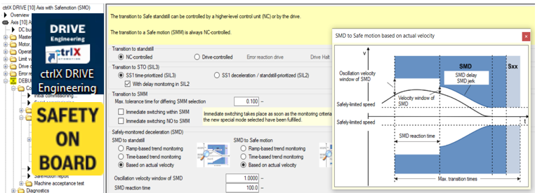
Next the parameterization in how to react on changes in operating status is parameterized. Normally in interpolating axes it is recommended to use the NC-controlled transition.

Fig. 28.: Parameterization of Change in operating status (sample for NC-controlled transition)
The recommendations are the following:
- Set Oscillation velocity window of SMD to around 0,2 to 0,5% of rapid speed used in the application
- Set SMD reaction time to the time needed for the jerk limited part of movement from rapid speed to standstill (usually the quotient: acceleration divided by jerk)
- Set Velocity window of SMD to around 0,2 to 0,5% of rapid speed used in the application
- Recommended is to set SMD jerk to “0”
- Set SMD delay to 60% of the acceleration used in the application
- Set the transition times taking into account the speed possible, the established acceleration and jerk plus a small safety margin of e.g. 50 ms
5.15. Error reaction settings
Next the parameterization in how to react on errors is parameterized.

Fig. 29.: Parameterization of Error reaction
The recommendations are the following:
- Set the tolerance times taking into account the speed possible, the established acceleration and jerk plus a small safety margin of e.g. 100 ms
- Set SMD-E oscillation velocity window of SMD to around 0,2 to 0,5% of rapid speed used in the application
- Set SMD-E reaction time to the time needed for the jerk limited part of movement from rapid speed to standstill (usually the quotient: acceleration divided by jerk)
- Set SMD-E velocity window of SMD to around 0,2 to 0,5% of rapid speed used in the application
- Set SMD delay to 50% of the acceleration used in the application
- Recommended is to set SMD-E jerk to “0”
5.16. Support function settings
Finally the parameterization is done in how support functions are set.

Fig. 30.: Parameterization of Support functions
6. Axis Validation
To ensure if the scaling both in the standard (non-safety) and the safety part of the runtime or firmware is correct the axis need to be validated.
Mind: Later on if the safety configuration isn´t changed this validation doesn´t need to be repeated even if the safety parameterization is changed.
Call up the “Easy startup mode”, select “Drive controlled positioning” and “Command value input”. Key in proper positioning velocity, acceleration, deceleration and jerk values and a position command value as a first position.
Additionally call up the menu sequence for “Axis validation”!

Fig. 31.: Validation of axis step 1
“Start” the movement of the drive to this first position. Put a marker at the mechanics for this first position, in here “0”.

Fig. 32.: Validation of axis step 2
Then press button “Next”!
Go on by pressing the button “Start” in the Axis validation menu!

Fig. 33.: Validation of axis step 3
As next action press button “Start measurement with axis motion”!

Fig. 34.: Validation of axis step 4 (1)
Key in a new position command value, in here e.g. 10 mm and start the movement

Fig. 35.: Validation of axis step 4 (2)
After finishing the movement (position is at 10 mm now) press the “Stop measurement” button!
Then switch “Drive off”! Axis travelled now in the standard part of the runtime (Firmware) by 10 mm. The SafeMotion feedback value difference from Validation start point to actual values is as well 10 mm. The same distance should be present on the mechanical side as well (from marker to the now present position).

Fig. 36.: Validation of axis step 4 (3)
Key in the measured distance at the mechanical side. If more or less the same value as measured by the menu press button “Confirm axis validation”!

Fig. 37.: Validation of axis step 5 (1)
If being in parameter or configuration mode, go to “DEBUG SafeMotion …”, press right hand mouse click and “Unlock SMO”!

Fig. 38.: Validation of axis step 5 (2)
Finally press the button “Confirm axis validation”! It is recommended to obtain the “Report”. Then “Finish” the menu!

Fig. 39.: Validation of axis step 5 (3)
Check if in “Diagnostics - SafeMotion” the axis is validated and safe.

Fig. 40.: Validation of axis (radio button of “Axis validated” and “Axis safe” in green)
7. SafeMotion Report
It is recommended to create the SafeMotion report by double clicking on the tree entry.

Fig. 41.: Create SafeMotion report (callup)
The SafeMotion report will be created.

Fig. 42.: Create SafeMotion report
Save the SafeMotion report.
The SafeMotion report should be included to the machine documentation papers. Whenever a device of the axis has to be replaced the then newly created SafeMotion report will show the serial number of the changed devices but the still be present exactly same axis identifier data and check sums.

Fig. 43.: Save SafeMotion report (identifier data and checksums)
This is to show that the SafeMotion parameters have been set correctly to the right axis and the right motor and amplifier components. In this way it provides proof that the correct parameter settings have been loaded in order to ensure personnel safety.
8. Serial Commissioning of SafeMotion
In the following sequence the procedure for serial commissioning of an axis with SafeMotion is shown.
Prerequisite is that the drive parameters of the standard runtime (non SafeMotion parameters) have been loaded. Then go to tree entry “Serial Commissioning! Select “Copy of an axis (1:1 copy)”!

Fig. 44.: Serial Commissioning of SafeMotion (select 1:1 copy)
Changeover to “Configuration mode”
Select the right parameter file! “Only load safety technology parameters image”! Then press button “Next”!

Fig. 45.: Serial Commissioning of SafeMotion (select parameter file)
Enter the axis identifier, if the one from the selected parameter file is correct ! Now press button “Load defaults procedure for SMO”!

Fig. 46.: Serial Commissioning of SafeMotion (enter axis identifier)
Then press button “Next”!
Now wait until parameter loading is finished!
Next step is to “Identify SafeMotion” to ensure that the parameters were loaded to the right device.

Fig. 47.: Serial Commissioning of SafeMotion (Identify SafeMotion)
If now the right axis is flashing red – green – green – red then press “Apply axis identifier” button!
Next a screen should pop up telling that the assignment was done correctly.
Now the serial commissioning is finished by pressing the button “Exit”.
After that the axis is in configuration mode and in all other axes of a safety zone the error F7035 is present. Change to Operation mode and quit the errors in all the other axes.
As final step it is recommended to create the Safety report for the axis with the new serial numbers of the devices (motor(s) and amplifier) used in the particular machine. This report should be added to the machine documentation. See chapter 7.
Record of revision: Version 03, 2022-07
Editorial Department: Drives Support [UwWe]

You must be a registered user to add a comment. If you've already registered, sign in. Otherwise, register and sign in.