
- Subscribe to RSS Feed
- Mark as New
- Mark as Read
- Bookmark
- Subscribe
- Printer Friendly Page
- Report Inappropriate Content
In the following we show to you how to correctly use analog inputs/outputs at ctrlX DRIVE.
Versions used
All the functions and screen shots are based on:
- ctrlX DRIVE Engineering version 01V14
- Runtime / Firmware version of drive AXS-V0308
or
- Runtime / Firmware version of drive AXS-V0210
Prerequisites
A connection to the ctrlX DRIVE has been successfully established, the device is correctly wired and 24 V are successfully put on. As well the engineering tool ctrlX DRIVE Engineering has been started.
1. Hardware overview
1.1. Standard devices
Single axes XCS or XMS (XG31 Pin 9 & 10)
Double axes XCD or XMD (XG31.1 and XG31.2 Pin 9 & 10)
The standard devices incorporate only one analog input.
This analog input is by default not pre-parameterized.
The user has to create the configuration according to his application and demand.

Fig. 1.: Analog Input - XG31.1
1.2. DA Option: (XG37, XG38)
e.g.: XCS2-W0023ARN-02AETT0NNDA-S03RSN2TE1N0NN
With the option DA a ctrlX DRIVEplus gets additional digital and analog Inputs and Outputs:
At XG37:
- 4 Inputs or Outputs (IO_1 to IO_4) (flexibly parameterized according to demands)
- 4 Inputs (I_5 to I_8)
- 4 Outputs (O_5 to O_8)

Fig. 2.: XG37
At XG38:
- 3 Analog Inputs (I_a_1 to I_a_3)
- 2 Analog Outputs (O_a_1 to O_a_2)

Fig. 3.: XG38
Resolution
Analog Inputs: (+/- 10V): 12bits
Analog Outputs: (+/- 10V): 10bits
2. Parameters to configure the analog inputs/outputs
2.1. Analog input parameters

Fig. 4.: XG31.1 - Analog Input Parameters
P-0-2900.x.1: Analog input, control word
Each instance of the parameter "P-0-2900.x.1" stands for one of the analog inputs.
x = 0: Analog input 1 (onboard)
x = 1: Analog input 1 (DA option)
x = 2: Analog input 2 (DA option)
x = 3: Analog input 3 (DA option)
The parameter is used for selecting the clock in which the analog input is processed, and for selecting the measuring range.
P-0-2900.x.2: Analog input, target parameter
In this parameter, enter the IDN of the parameter to which a value is to be written that corresponds to the voltage or the current at the respective analog input. Only such IDNs can be entered in "P-0-2900.x.2" that are contained in " P-0-0212, Analog input, list of assignable parameters".
P-0-2900.x.3: Analog input, nominal value
This parameter is used for scaling the analog input for the individual assignment. The nominal value is always the value, which is generated at the upper signal limit of the measuring range (without consideration of offset).
The unit, the decimal places and the data type are determined by the parameter assigned in " P-0-2900.x.2, Analog input, target parameter".
P-0-2900.x.4: Analog input, offset
The offset of the analog input is set in this parameter. The offset corresponds to the value that the assignment parameter has with a signal value of 0. If "0" is not included in the selected measuring range, the offset refers to the lower limit of the signal range.
The unit, the decimal places and the data type are determined by the parameter assigned in " P-0-2900.x.2, Analog input x, target parameter".
P-0-2900.x.5: Analog input, filter time
To improve the signal quality of the analog input, a filter can be activated and set via the parameter "P-0-2900.x.5".
P-0-2900.x.8: Analog input, lower limit of signal range
This parameter contains the lower limit of the selected measuring range. If a user-defined measuring range is selected, this parameter can be written. Otherwise, it is used for display purposes only.
The lower limit cannot be greater than or equal to the upper limit.
P-0-2900.x.9: Analog input, upper limit of signal range
This parameter contains the upper limit of the selected measuring range. If a user-defined measuring range is selected, this parameter can be written. Otherwise, it is used for display purposes only.
The upper limit cannot be less than or equal to the lower limit.
P-0-2900.x.10: Analog input, wire break threshold
The parameter "P-0-2900.x.10" specifies the threshold value for wire break monitoring. Wire break monitoring is available individually for each input. The monitoring function is active as soon as a value greater than "0" is entered in the parameter.
Using the parameter " P-0-2900.x.1", you can configure whether the wire break message is signalled as an error or as a warning.
P-0-2901.0.1: Analog input, control word
Parameter for controlling the automatic adjustment of the analog inputs.
P-0-2901.0.2: C2800 Analog input, adjustment command
Command for the automatic adjustment of an analog input.
P-0-2901.0.3: Analog input, maximum value for adjustment
This parameter provides a defined command value for determining the value of " P-0-2900.x.3".
The „x“ represents the analog input selected in " P-0-2901.0.1; bit 0-3".
P-0-0210: Analog input 1
This parameter is used to display the input voltage in volts currently applied to analog input 1. The parameter value is updated in the controller cycle or every 2ms.
2.2. Analog output parameters

Fig. 5.: XG31.1 - output parameter
P-0-0414: DA Analog output 1
This parameter specifies the voltage value, output via the analog output 1 of the "DA" option module.
P-0-0415: DA Analog output 2
This parameter specifies the voltage value, output via the analog output 2 of the "DA" option module.
P-0-2901.0.1: Analog input, control word
Parameter for controlling the automatic adjustment of the analog inputs.
P-0-2911.x.1: Analog output, control parameter
Each instance of the parameter "P-0-2911.x.1" stands for one of the analog outputs.
x = 0: Analog output 1 (DA option)
x = 1: Analog output 2 (DA option)
The analog output source is defined via the control word of the assignment.
P-0-2911.x.3: Analog output: Parameter selection
In this parameter, enter the IDN of the parameter. The current value of the parameter is to be output to the corresponding analog output. The source of the analog output is set in " P-0-2911.x.1". Only ident numbers contained in " P-0-0426, Analog output IDN list of assignable parameters" can be entered in this parameter.
P-0-2911.x.4: Analog output: Offset
An offset is set for the corresponding analog output via this parameters. The offset is added to the current signal value of the drive parameter during the output.
P-0-2911.x.5: Analog output: Value range
The value range of the drive parameter is set for the corresponding analog output via this parameter which is to be output to the corresponding analog output .
P-0-2911.x.6: Analog output: Signal range, lower limit
Via this parameter, the lower signal range limit of the analog output is defined. In connection with parameter " P-0-2911.x.7" (upper limit), the signal range of the analog output is defined on which the drive parameter signal is to be mapped. Furthermore, this parameter is used to define a lower limit for the output to the analog output. This means, the lowest voltage that can be output or the lowest current that can be output is specified. If as a result of mapping the current signal of the drive parameter, a lower signal or lower current is generated, the output value is limited to the value in parameter P-0-2911.x.6.
The following conditions have to be complied with when entering this parameter:
- P-0-2911.x.6 >= Minimum voltage (e.g. -10 V) / minimum current of the analog output (e.g. 4mA) containing the assignment
- P-0-2911.x.6 < Maximum voltage (e.g. 10 V) / maximum current of the analog output (e.g. 20mA) containing the assignment
- P-0-2911.x.6 < P-0-2911.x.7
P-0-2911.x.7: Analog output: Signal range, upper limit
Via this parameter, the upper limit of the signal range is defined by the analog output. In connection with parameter P-0-2911.x.6 (lower limit), the value range of the analog output is defined on which the drive parameter signal is to be mapped. Furthermore, this parameter is used to define an upper limit for the output to the analog output. This means, the highest voltage that can be output or the highest current that can be output is specified. If as a result of mapping the current signal of the drive parameter, a higher voltage or higher current is generated, the output value is limited to the value in parameter P-0-2911.x.7.
The following conditions have to be complied with when entering this parameter:
- P-0-2911.x.7 > Minimum voltage (e.g. -10V) / minimum current of the analog output (e.g. 4mA), it is assigned to
- P-0-2911.x.7 <= Maximum voltage (e.g. 10V) / maximum current of the analog output (e.g. 20mA), it is assigned to
- P-0-2911.x.7 > P-0-2911.x.6
See also Functional Description "Analog outputs"
3. Configuration of the analog in/outputs
3.1 Analog input, list of assignable parameters
IDN P-0-0212.0.0 (Firmware ASX-V0308)


Fig. 6.: P-0-0212
3.2 Analog otput, list of assignable parameters
IDN P-0-0426.0.0 (Firmware AXS-V0308)


Fig. 7.: P-0-0426
4. Application examples
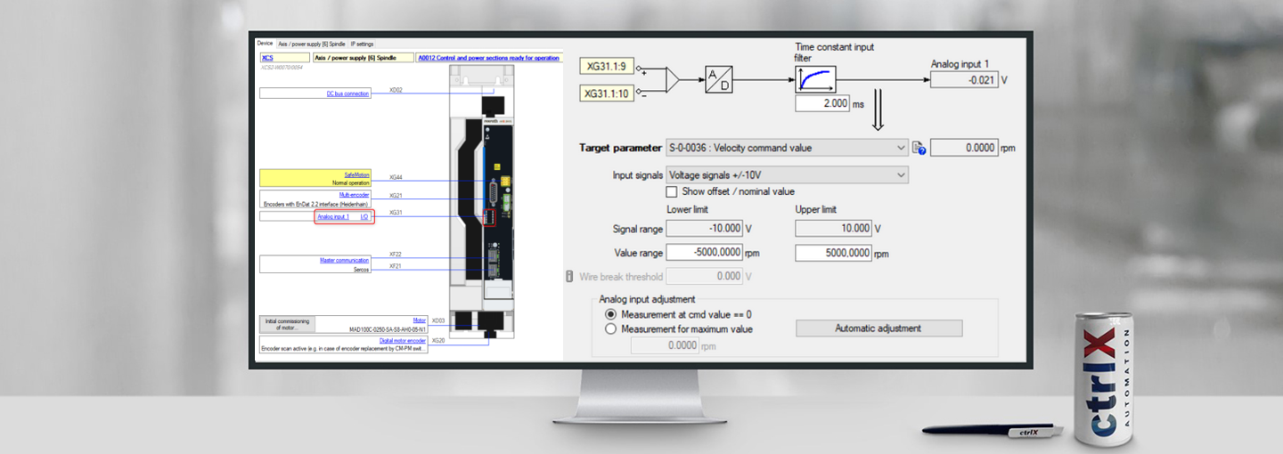
4.1. Velocity control via analog input
The most common application of using an analog input is velocity control.
Example: 0-10V velocity setpoint on XG31.1 Pin9 & 10 => motor speed of 0-5000rpm
See as well: How-To
4.1.1 Parameter setting analog input

Fig. 8.: Velocity control – analog input
4.1.2 Set operating mode

Fig. 9.: Velocity control – operation mode
4.1.3 Configuration velocity control
The fields marked green are used to parameterize a ramp function in the velocity setpoint values.
Limit values are entered in the orange fields.

Fig. 10.: Velocity control – configuration
4.2. Analog output of the motor power
Example: The motor power 150W is signalled via the analog output XG38, Pin 11 & 12 (0-10V)

Fig. 11.: Output 1 DA XG38
- Signal source: Switch to parameter output
- Signal selection: Activate motor power S-0-0385
- Lower Limit / Signal range: 0V should be output at the motor power of 0W
- Upper Limit / Signal range: 10V should be output at the motor power of 150W
- Lower Limit / Value range: 0V should be output at the motor power of 0W
- Upper Limit / Value range: 10V should be output at the motor power of 150W
Overview of the connection points of the DA circuit board

Fig. 12.: DA Overview

You must be a registered user to add a comment. If you've already registered, sign in. Otherwise, register and sign in.